Snare drum accessory

a technology of snare drums and accessories, applied in the field of snare drum accessories, can solve the problems of not being able to continuously adjust the control mechanism, and achieve the effect of inherent friction

Inactive Publication Date: 2006-11-30
JEFFRIES WALTER B +1
View PDF19 Cites 28 Cited by
  • Summary
  • Abstract
  • Description
  • Claims
  • Application Information

AI Technical Summary

Benefits of technology

[0006] According to the present invention we control the selective tightening of the snare wires by a camming mechanism that has an inherent level of friction which allows it to be reliably set at an extreme upper position of

Problems solved by technology

In presently standard snare drums the T bracket is movable between two extreme positions, but the control mechanism

Method used


Image

  • Snare drum accessory
  • Snare drum accessory
  • Snare drum accessory

Examples


Embodiment Construction

(FIGS. 1-5, inclusive)

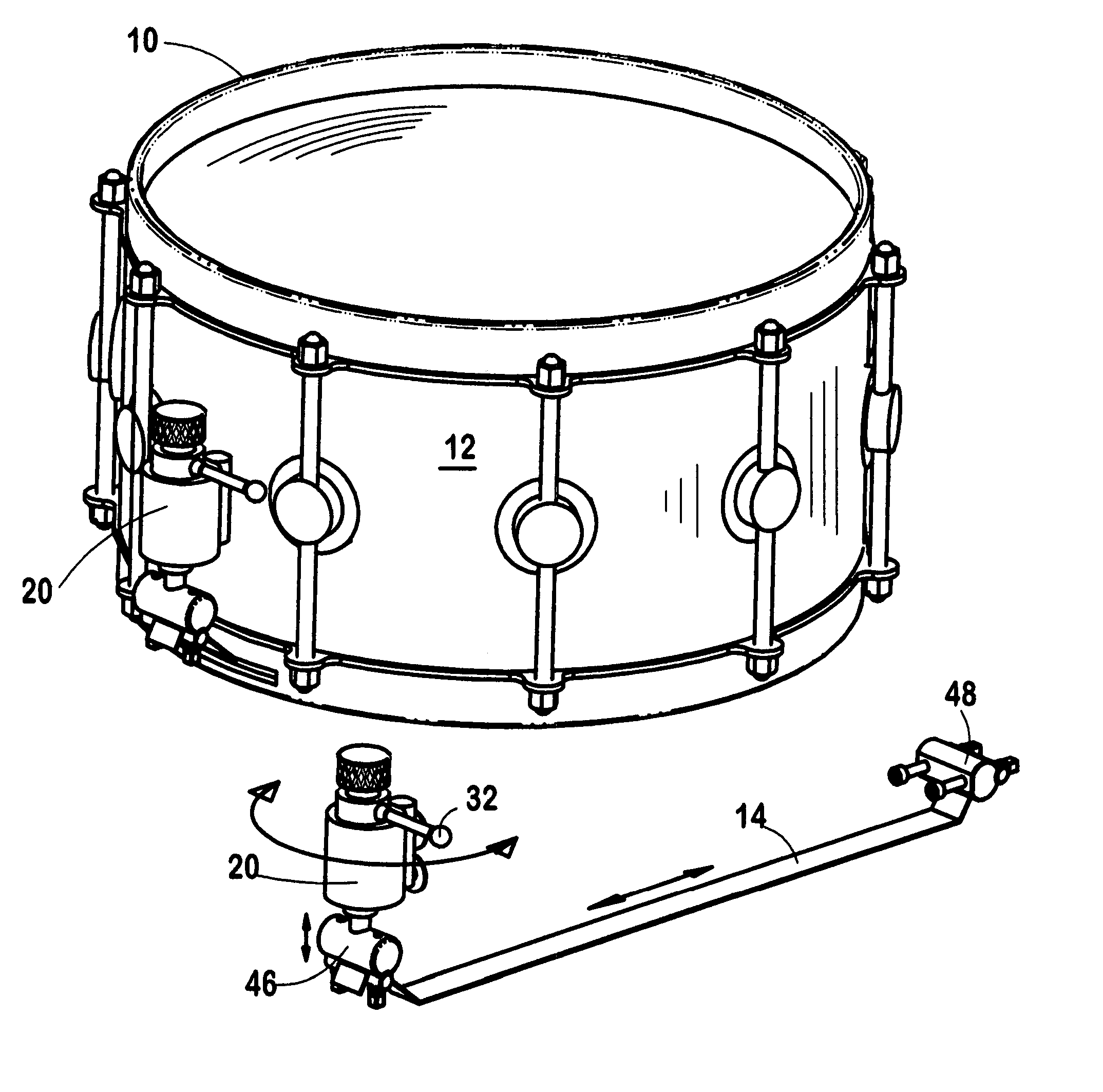
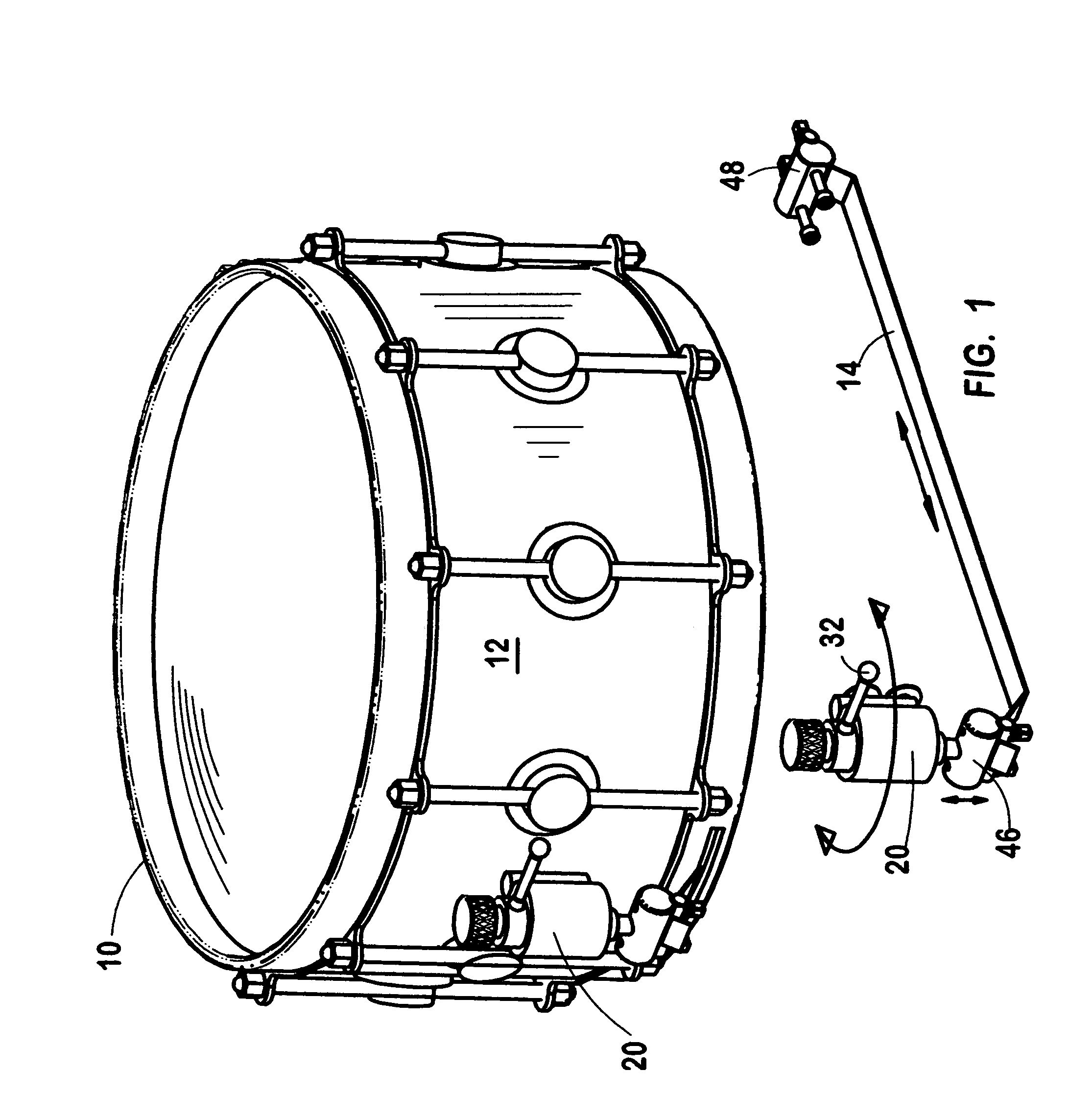
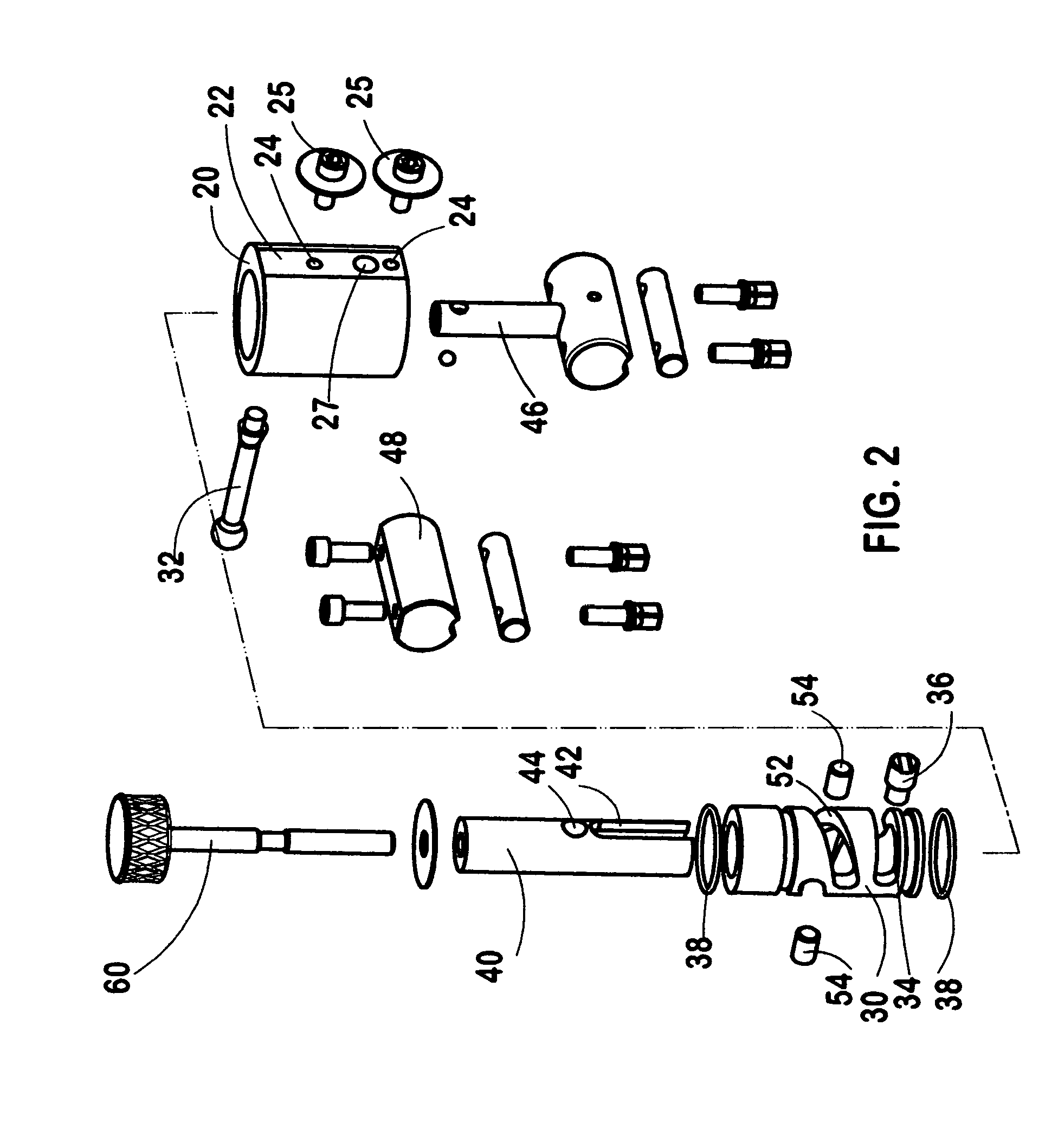
[0014] More particularly, according to the presently preferred form of our invention a snare drum 10 has a control housing 20 attached to an outer surface of the drum shell 12 which contains a drive cylinder 30 that extends vertically and is rotatable relative to the housing. Inside the drive cylinder 30 there is a vertically extending lifting rod 40 that is vertically movable within the drive cylinder but does not rotate relative to either the control housing or the drive cylinder. The lower end of the lifting rod 40 is secured to one end of the snare wires 14, for selectively tightening them when the lifting rod is lifted up.

[0015] A hand-operated camming mechanism is cooperatively formed by the drive cylinder and the lifting rod for selectively raising or lowering the lifting rod within the drive cylinder. The camming mechanism has an inherent level of friction which allows it to reliably set the lifting rod at either an extreme upper position of adjustment...


PUM


Abstract

An adjustment mechanism for selectively tightening the snare wires of a snare drum, having a camming mechanism cooperatively formed by two concentric members with an inherent level of friction that allows it to be reliably set at either extreme position of adjustment of the tightness of the snare wires or at any desired intermediate position of adjustment, thus allowing the musician a full range of choice of the musical tones or effects to be produced by the snare wires.

Description

PRIORITY CLAIM [0001] This application claims the priority of our provisional application Ser. No. 60 / 685,333 filed May 26, 2005.FIELD OF THE INVENTION [0002] This invention relates to the field of musical instruments, and particularly snare drums. BACKGROUND OF THE INVENTION [0003] A typical snare drum has a cylindrical shell with drumheads of flat circular configuration mounted on both its top and bottom ends. Each drumhead is surrounded by a circumferential rim. A group of snare wires extend beneath and across the lower drumhead, in a normally loose configuration. A mechanism which allows the musician to tighten the snare wires causes them to impact the bottom surface of the lower drumhead, generating sounds of a distinctive character, since the vibratory motions of the bottom drumhead are then modified by contact with the snare wires. [0004] In the presently standard snare drum, at one of their ends the snare wires are supported in abutting relationship to the associated circumf...

Claims


Application Information

Patent Timeline
IPC IPC(8): G10D13/02
CPCG10D13/025G10D13/02G10D13/18
Inventor JEFFRIES, WALTER B.HAUTH, TYLER D.
Owner JEFFRIES WALTER B
Why Eureka
Try Eureka