Radar sensor for receiving radar wave while judging existence of wave attenuator

Active Publication Date: 2009-08-20
DENSO CORP +1
View PDF5 Cites 12 Cited by
  • Summary
  • Abstract
  • Description
  • Claims
  • Application Information

AI Technical Summary

Benefits of technology

[0016]Therefore, when the level of one receiving channel is temporarily reduced due to the reception of multi-path reflected waves or the like, the receiving channel is set as a candidate channel. Therefore, the preliminary judgment variable of the receiving channel is repeatedly incremented for a short time. However, the increase of the final judgment variable is not started until the preliminary judgment variable reaches the preliminary judgment value. Accordingly, the sensor can prevent a misjudgment based on multi-path reflected waves or the like that a wave attenuator attenuates the reflected radar wave directed toward the wave transmission member.
[0017]Further, a wave attenuator is sometimes moved on/over the wave transmission member. In this case, the attenuator first attenuates the radar wave directed toward one receiving channel and attenuates the radar wave directed toward another channel at a next time. Therefore, even when the preliminary judgment variable of one receiving channel once reaches the preliminary judgment value to increase the final judgment variable, the receiving channel is set as a candidate for a channel (e.g., anon-candidate channel) which receives electric power of the received signal without being influenced by any wave attenuator, and the preliminary judg

Problems solved by technology

However, the radar sensor is exposed to the open air, so that various things such as turbid water, snow, dust, mud and the like are easily attached to a surface of a protecting member covering the receiving antenna of the sensor.
Therefore, the performance for detecting the object in the radar sensor is undesirably degraded, so that the reliability in the trailing control and the predicting control is lowered in the radar sensor.
When this continuation time exceeds a predetermined period, the radar sensor judges that the performance degradation is continuously caused by various things soiling the surface of the protecting member.
However, as the numbe

Method used


Image

  • Radar sensor for receiving radar wave while judging existence of wave attenuator
  • Radar sensor for receiving radar wave while judging existence of wave attenuator
  • Radar sensor for receiving radar wave while judging existence of wave attenuator

Examples


Example

[0028]An embodiment of the present invention will now be described with reference to the accompanying drawings.

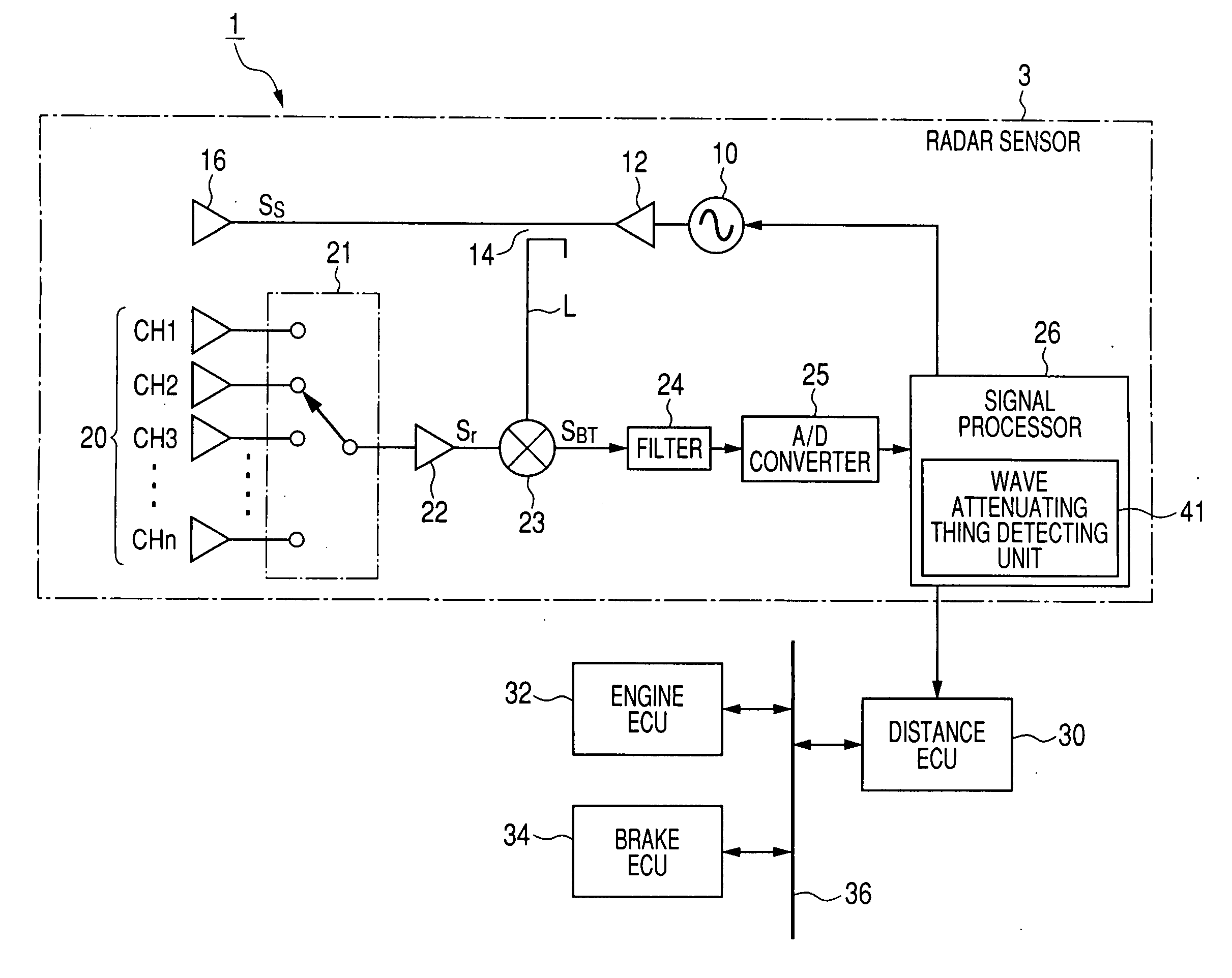
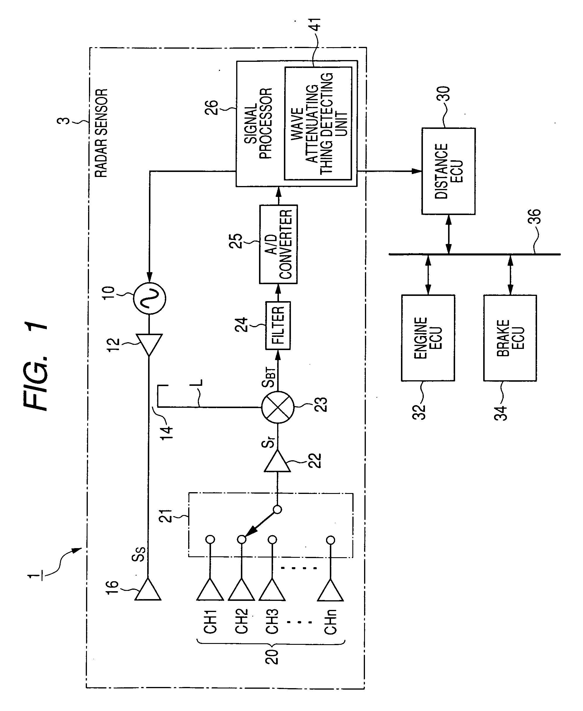
[0029]FIG. 1 is a block diagram of a vehicle control system 1 having a radar sensor according to this embodiment.

[0030]As shown in FIG. 1, this vehicle control system 1 has a radar sensor 3 located on a front surface of the current vehicle to detect a target object (e.g., a preceding vehicle, a roadside object, an obstacle or the like) placed in front of the vehicle in a predetermined detecting area, a distance electronic control unit (ECU) 30 acting as an adaptive cruise control system to control a distance between the radar sensor 3 and the object according to information transmitted from the sensor 3, an engine ECU 32 for controlling a driving force produced in an engine of the vehicle according to an engine control signal transmitted from the distance ECU 30 though a local area network (LAN) communication bus 36, and a brake ECU 34 for controlling a braking torque produ...


PUM


Abstract

A radar sensor receives a radar wave signal through a radome in each of antennas while judging existence of an attenuating thing in a detecting unit. This unit extracts a maximum level channel from receiving channels assigned to the antennas every modulation period, calculates a difference in signal level between the maximum level channel and each receiving channel every modulation period, sets each receiving channel corresponding to large level differences in one measuring period including plural modulation periods as a candidate channel every measuring period, increments a preliminary variable of each candidate channel every measuring period, increases a final variable each time the preliminary variable of at least one receiving channel reaches or exceeds a preliminary value in one measuring period, and judges in response to the final variable reaching a final value that the attenuating thing attenuates the radar wave directed toward the radome.

Description

CROSS-REFERENCE TO RELATED APPLICATION[0001]This application is based upon and claims the benefit of priority of the prior Japanese Patent Application 2008-34770 filed on Feb. 15, 2008, so that the contents of which are incorporated herein by reference.BACKGROUND OF THE INVENTION[0002]1. Field of the Invention[0003]The present invention relates generally to a radar sensor which receives a radar wave, reflected from a target object and transmitted through a wave transmission member, in a plurality of antenna elements, and more particularly to the radar sensor which judges the existence of a wave attenuator attenuating the radar wave directed toward the member.[0004]2. Description of Related Art[0005]A millimeter wave radar sensor disposed on a vehicle has been used for a vehicle trailing control and / or a vehicle collision predicting control. In this radar sensor, a millimeter wave is transmitted from a transmitting antenna to a target object (e.g., an obstacle or a preceding vehicle)...

Claims


Application Information

Patent Timeline
IPC IPC(8): G01S3/14G01S3/28G01S13/58G01S13/93B60K31/00B60R21/00B60W30/16G01S7/03G01S7/40G01S13/931G08G1/16
CPCG01S7/032G01S2013/9389G01S13/42G01S13/931G01S2013/9357H01Q1/3233H01Q3/40H01Q21/06G01S2007/4039G01S2013/9325G01S2013/9346G01S2013/935G01S2013/9353G01S2013/9375G01S7/4017G01S13/345G01S2013/9319G01S2013/93185G01S2013/9322G01S2013/93275G01S2013/932G01S2013/93271G01S7/4039
Inventor SAMUKAWA, YOSHIEABE, YOSHIHIROKAWAKUBO, ATSUSHI
Owner DENSO CORP
Why Eureka
Try Eureka