

Vertical synchronous signal detection circuit
- Summary
- Abstract
- Description
- Claims
- Application Information
AI Technical Summary
Benefits of technology
Problems solved by technology
Method used
Image

Examples
first embodiment
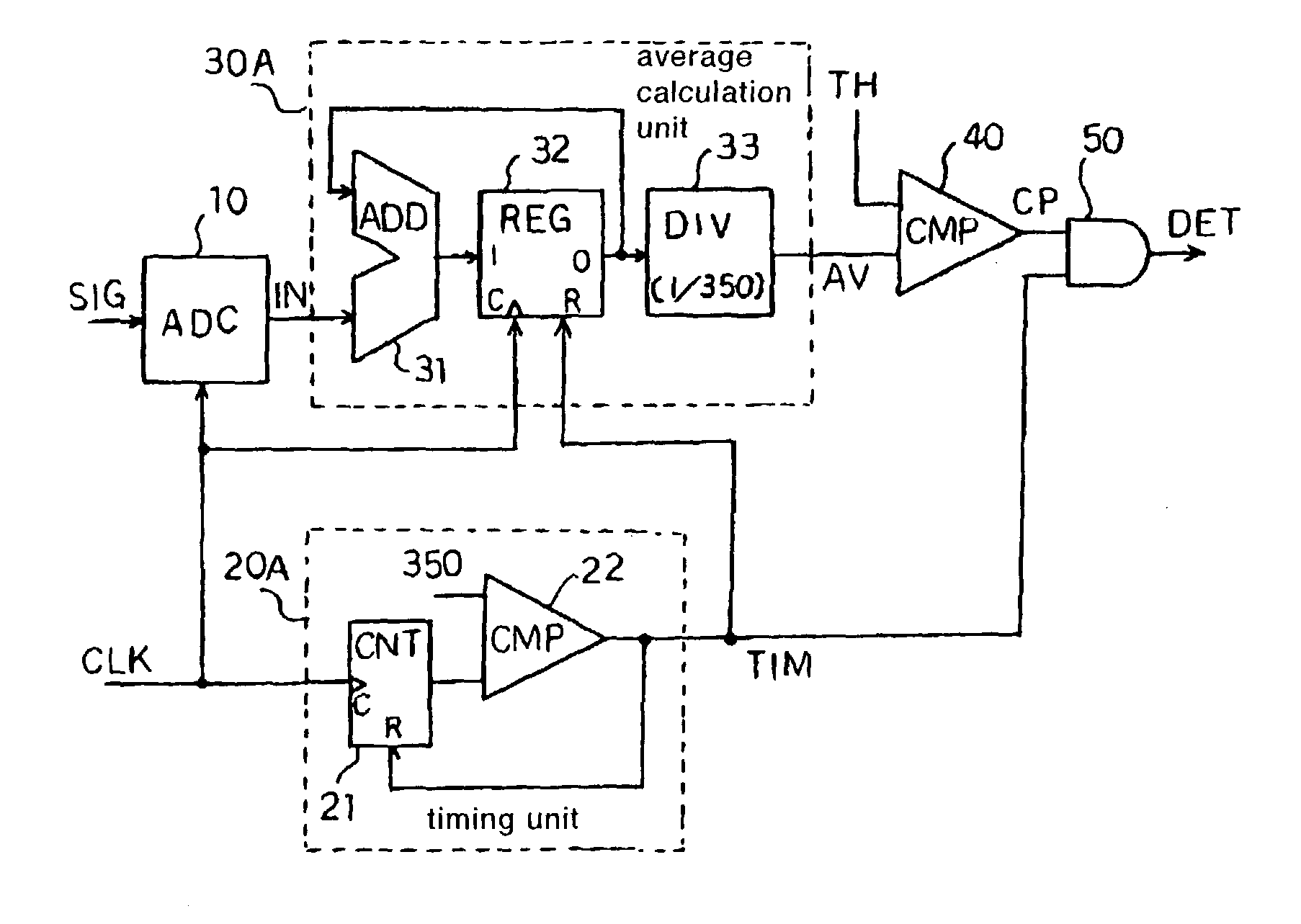
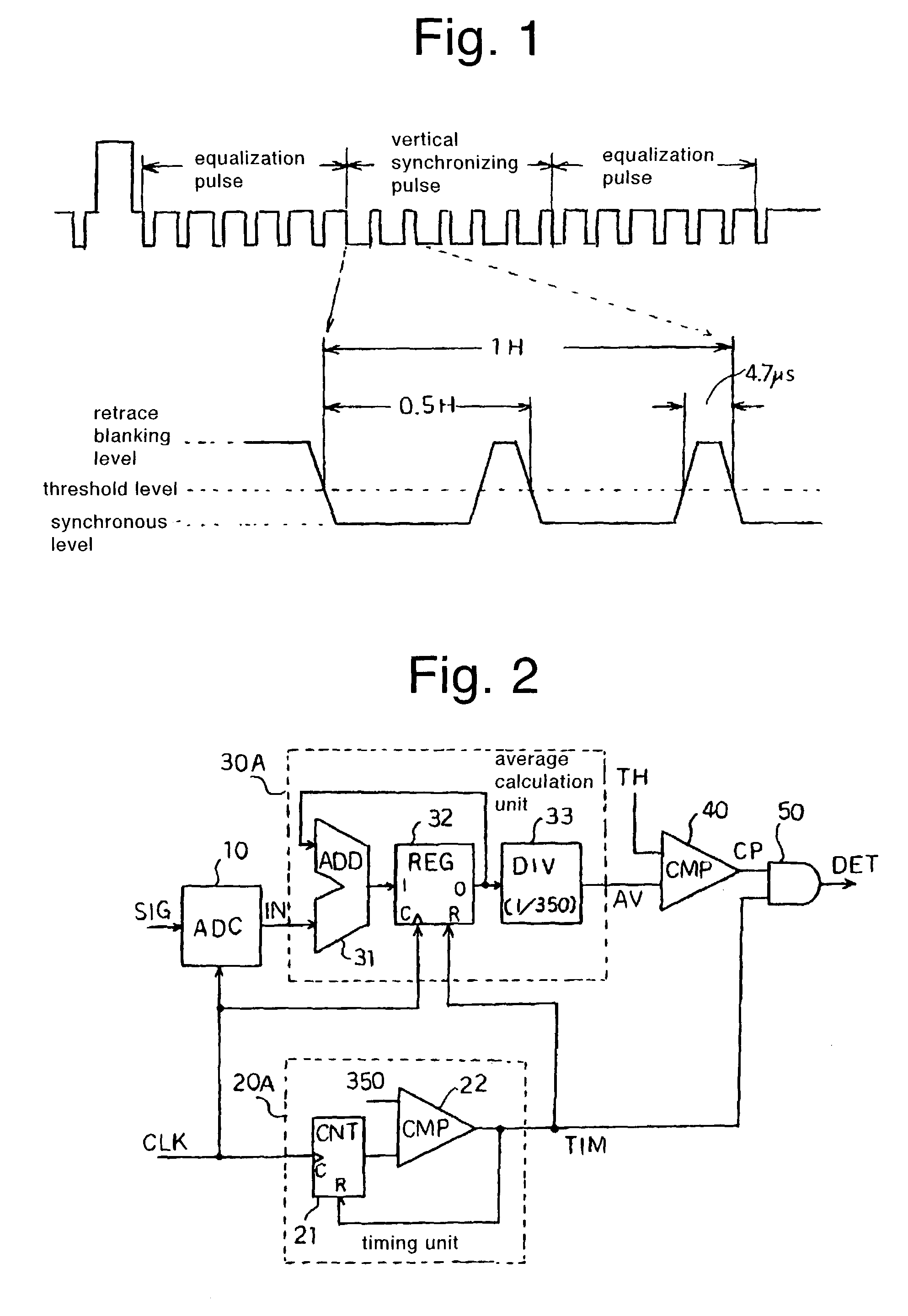
[0024]FIG. 2 is a configurational diagram of a vertical synchronous signal detection circuit showing the present invention.
[0025]The vertical synchronous signal detection circuit has an analog-to-digital converter (hereinafter called an “ADC”) 10 which samples, for example, a composite video signal SIG of an NTSC system with a clock signal CLK of 13.5 MHz and converts the same to a digital input signal IN, and a timing unit 20A which generates a timing signal TIM, based on the clock signal CLK.
[0026]The timing unit 20A outputs the timing signal TIM for vertical synchronous signal detection in a predetermined cycle defined in every 350 clocks and comprises a counter (CNT) 21 which counts the clock signal CLK, and a comparator 22 which compares a count value of the counter 21 with a constant number (350 in the present embodiment). The comparator 22 outputs the timing signal TIM when the two input values have coincided with each other.
[0027]Further, the vertical synchronous signal dete...
second embodiment
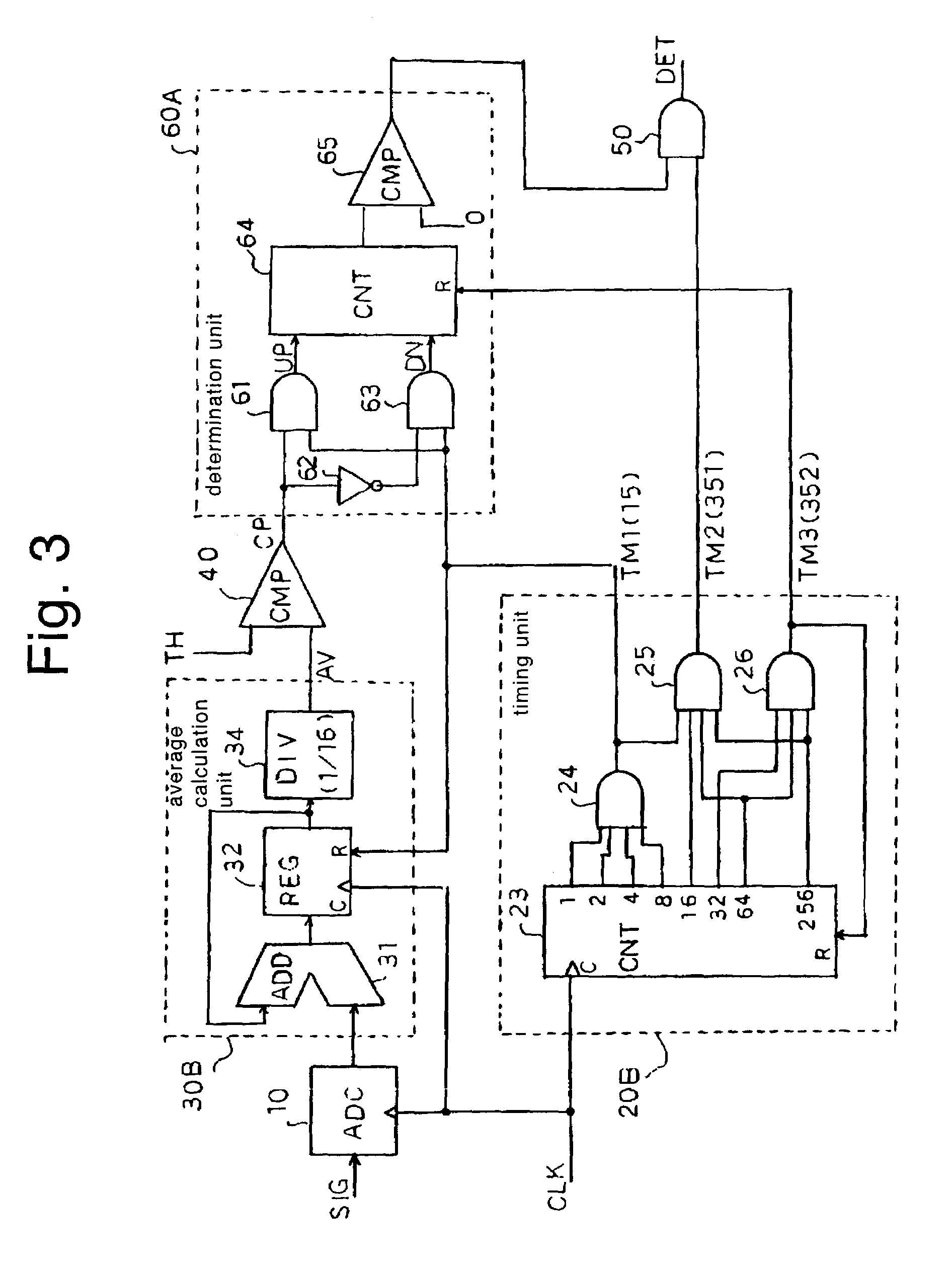
[0036]FIG. 3 is a configurational diagram of a vertical synchronous signal detection circuit showing the present invention. Elements of structure common to those in FIG. 2 are respectively identified by common reference numerals.
[0037]The vertical synchronous signal detection circuit has an ADC 10 which samples a composite video signal SIG with a clock signal CLK and converts it into a digital input signal IN, and a timing unit 20B which generates timing signals TM1, TM2 and TM3, based on the clock signal CLK.
[0038]The timing unit 20B comprises a 9-digit binary counter 23 which counts the clock signal CLK, and ANDs 24 through 26 which decode a count value of the binary counter 23 and thereby output timing signals TM1 through TM3, respectively. The AND 24 sets the timing signal TM1 to “H” each time the count value of the binary counter 23 reaches a multiple of 16. Further, the ANDs 25 and 26 respectively output timing signals TM2 and TM3 of “H” when the count value of the binary coun...
third embodiment
[0051]FIG. 4 is a configurational diagram of a vertical synchronous signal detection circuit showing the present invention. Elements of structure common to those in FIG. 3 are respectively identified by common reference numerals.
[0052]The vertical synchronous signal detection circuit includes an ADC 10 which samples a composite video signal SIG with a clock signal CLK and converts it into a digital input signal IN, and a timing unit 20C which generates timing signals TM1 and TM2, based on the clock signal CLK. The timing unit 20C is one wherein the AND 26 for generating the timing signal TM3 is omitted from the timing unit 20B in FIG. 3.
[0053]The vertical synchronous signal detection circuit has a comparator 40 which compares the input signal IN converted by the ADC 10 with a threshold level TH and thereby outputs a compare signal CP. The compare signal CP is supplied to a determination unit 60B.
[0054]The determination unit 60B comprises an updown counter 66 and comparators 67 and 6...
PUM
 Abstract
Description
Claims
Application Information