Device for inductively transmitting energy and method for operating an inductive energy-transmission device

Inactive Publication Date: 2016-03-10
ROBERT BOSCH GMBH
View PDF3 Cites 3 Cited by
  • Summary
  • Abstract
  • Description
  • Claims
  • Application Information

AI Technical Summary

Benefits of technology

[0010]An important advantage of the present invention is that absolutely no interfering foreign bodies are therefore located in the intermediate space between transmitting coil and receiving coil during the entire energy transmission. Intruding foreign bodies could otherwise significantly jeopardize the energy transmission. For example, animals which enter into the intermediate space between transmitting coil and receiving coil can suffer injuries due to the highly magnetic field. In addition, there is the risk that intruding objects, in particular objects containing metal, heat up on account of the strong magnetic field and can even catch fire in some cases. Such an entry of animals as well as from other foreign bodies can be reliably detected by means of the inventive monitoring of the intermediate space. If need be, suitable measures can subsequently be initiated.
[0011]A further advantage of the invention is that the magnetic field of the energy transmission is not disturbed particularly by means of an optical monitoring of the intermediate space between transmitting and receiving coil. The magnetic field for the energy transmission and the light beams of the monitoring device do not influence one another; thus enabling the energy transmission to take place in an unimpeded manner without being influenced in any way by the optical monitori

Problems solved by technology

Intruding foreign bodies could otherwise significantly jeopardize the energy transmission.
For example, animals which enter into the intermediate space between transmitting coil and receiving coil can suffer injuries

Method used


Image

  • Device for inductively transmitting energy and method for operating an inductive energy-transmission device
  • Device for inductively transmitting energy and method for operating an inductive energy-transmission device
  • Device for inductively transmitting energy and method for operating an inductive energy-transmission device

Examples


Example

[0025]The drawings depicted in the figures are in part perspective depictions of elements which, for reasons of clarity, are not necessarily depicted true to scale. Similar reference signs generally denote similar or similarly functioning components.

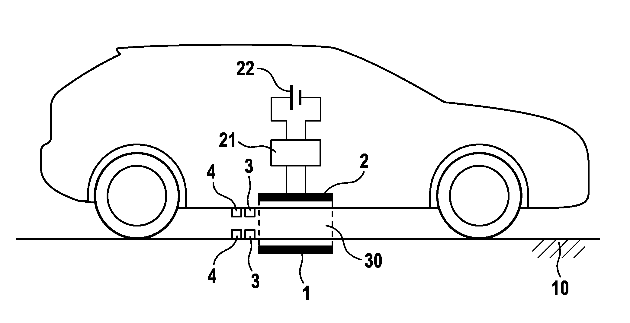
[0026]FIG. 1 shows a vehicle 20 which is parked over an inductive charging station. The vehicle 20 is parked in such a manner that the receiving coil 2 of the vehicle 20 is disposed above the transmitting coil 1. Due to the required ground clearance of the vehicle 20, an intermediate space 30 with an air gap exists between the ground 10 in which the transmitting coil 1 is disposed and the underside of the vehicle 20 in which the receiving coil 2 is located. This intermediate space 30 comprising the air gap can thereby amount to a plurality of centimeters. In the case of vehicle models typical today, air gaps between 15 and 25 cm are to be expected. Other sizes for the intermediate space between ground 10 and underside of the vehicle are ...


PUM


Abstract

The present invention relates to the monitoring of an intermediate space, in particular the air gap, between a transmitting coil and a receiving coil during inductive energy transmission. Said intermediate space is monitored by means of an optical monitoring device. By means of optical monitoring of the air gap between the transmitting coil and the receiving coil, the entry of an object can be reliably detected without the magnetic field of the inductive energy transmission being influenced.

Description

BACKGROUND OF THE INVENTION[0001]The present invention relates to a device for inductively transmitting energy from a transmitting coil to a receiving coil spaced apart from the transmitting coil as well as to a method for operating an inductive energy-transmission device.[0002]Electric vehicles are usually equipped with an electric energy store, for example a traction battery, which provides the electric energy for the drive. If this electric energy store is completely or partially discharged, the electric vehicle has to head for a charging station, at which the energy store can be recharged. Up until now, the electric vehicle is usually connected to the charging station by means of a cable connection. This connection must typically be manually produced by the user. As a result, it is required that the charging station and the electric car have a connecting system that corresponds to each other.[0003]In addition, wireless charging systems for electric vehicles are also occasionally...

Claims


Application Information

Patent Timeline
IPC IPC(8): B60L11/18G01V8/10H02J5/00
CPCB60L11/182G01V8/10H02J5/005B60L3/00Y02T90/14Y02T10/7072B60L53/124Y02T10/70H02J50/10H02J50/80H02J50/60Y02T90/12B60L53/12
Inventor ECKERT, BERND
Owner ROBERT BOSCH GMBH
Why Eureka
Try Eureka