
Method and system for configuring radio interface in a communication system

a radio interface and communication system technology, applied in the field of method and system for configuring radio interface in a communication system, can solve the problems of inability of the base station to carry out any measurement relating to the transmission conditions of the mobile station, limited physical resources in the frequency band, and must be used economically, and achieve the effect of reliably setting the transmission time immediately

Inactive Publication Date: 2007-01-23
SIEMENS AG
View PDF6 Cites 11 Cited by
  • Summary
  • Abstract
  • Description
  • Claims
  • Application Information

AI Technical Summary

Benefits of technology

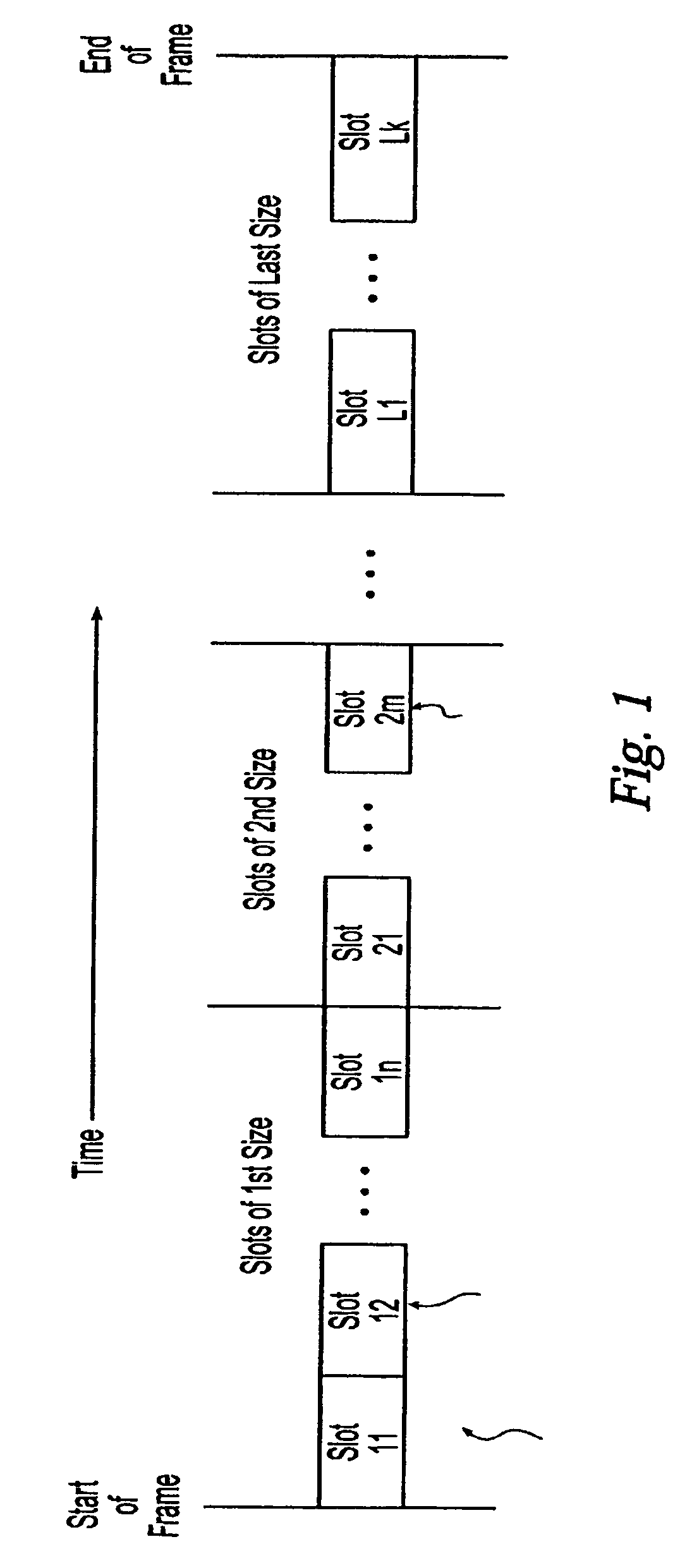
[0014]The proportion of time slots for adjacent cell measurements can be further increased if less configuration data is transmitted (for example only the timing advance) or only a small number of mobile stations need to be supplied. In this case, cyclic adaptation of the combination sequence may be provided. Such adaptation improves the matching of the signalling complexity to the actual requirements of the mobile stations for packet data transmissions.
[0026]The offset value is advantageously chosen such that the range which corresponds to it is greater than the distance which the mobile station can travel between two transmissions for timing advance definition at the maximum permissible speed. This ensures that, even if the mobile station is travelling at maximum speed, the transmission time immediately can be set reliably.

Problems solved by technology

For example, in mobile radio systems such as the GSM mobile radio system (Global System for Mobile Communications), the physical resources in the frequency band—[lacuna] [lacuna] number of frequency channels and time slot—are limited and must be used economically.
However, as long as there is no transmission from the mobile station to the base station, it is impossible for the base station to carry out any measurements relating to the transmission conditions from the mobile station.
The latter leads, for example, to an excessive, or even maximum, transmission power setting.

Method used


Image

  • Method and system for configuring radio interface in a communication system
  • Method and system for configuring radio interface in a communication system
  • Method and system for configuring radio interface in a communication system

Examples


Embodiment Construction

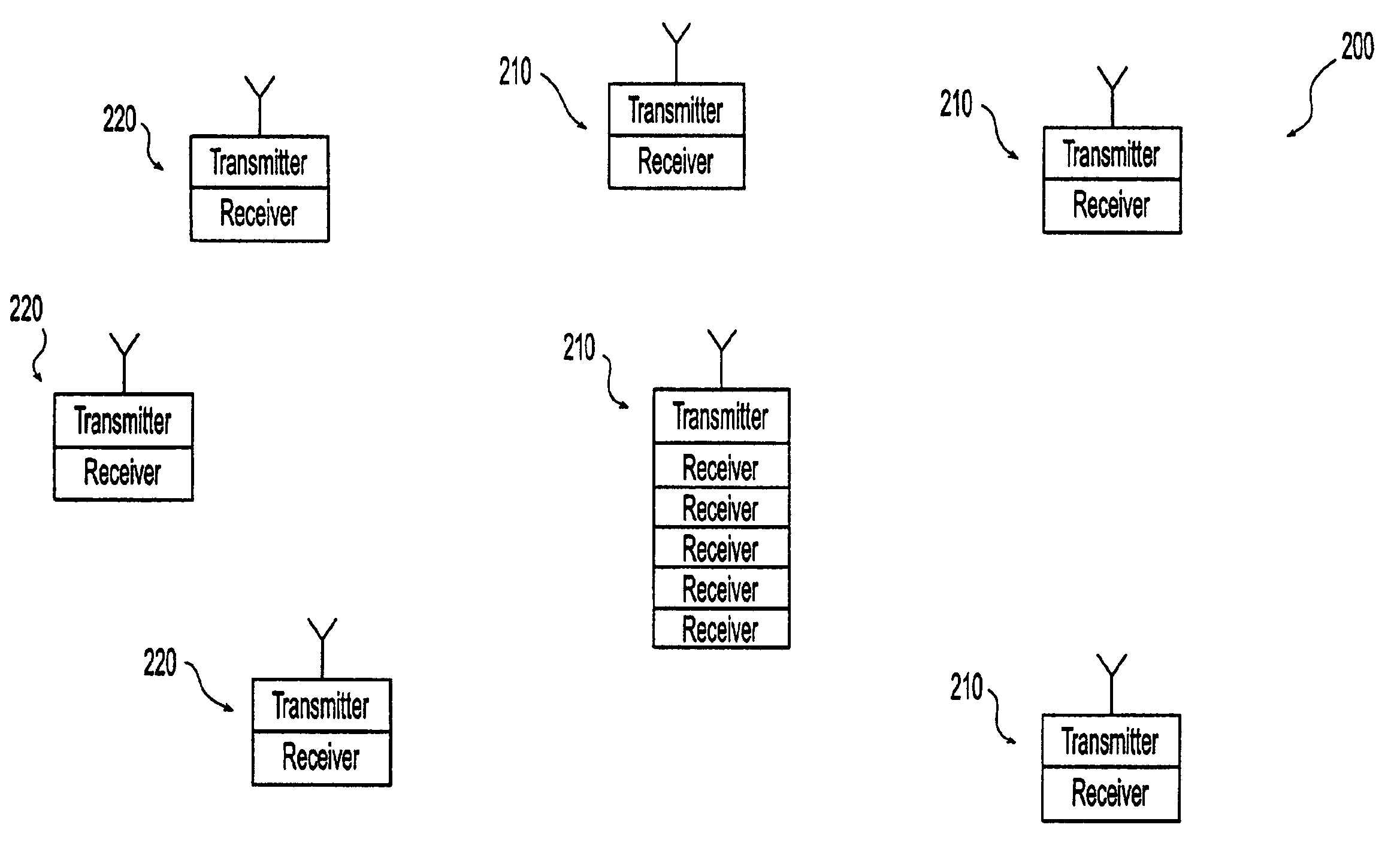
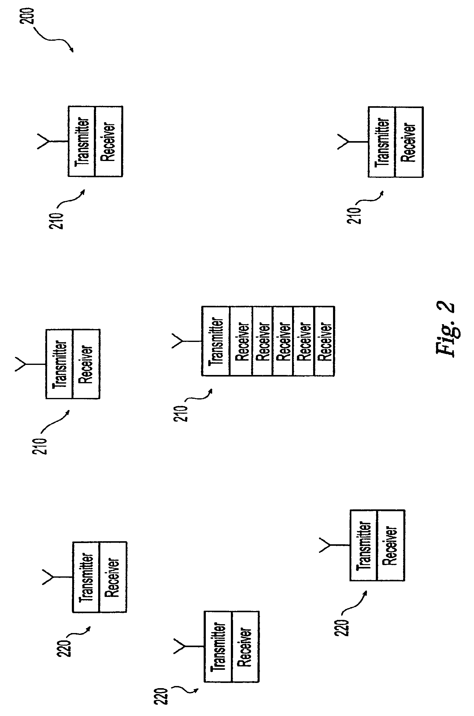
[0033]The time-division multiplex mobile radio system according to FIG. 1 is, for example, a GSM mobile radio network GSM which contains at least one base station system BSS with a control device BSC and base station BS. Mobile stations MS are located in the radio zone of an illustrated base station BS. The base station system BSS provides the link to other devices in the GSM mobile radio network GSM.

[0034]These other devices are, for example, a mobile switching center MSC and a unit for providing interworking functions IWF. The interaction of the mobile switching center MSC and interworking functions IWF results in a packet switching center, which is also called a GSN (GPRS support node). This packet switching center is connected to an MSC for voice switching or, alternatively, it could be implemented as a remote, dedicated unit.

[0035]The GSM mobile radio network GSM can be connected to other communications networks. For example, another communications terminal KEG can be connected...


PUM


Abstract

A method and system for configuring a radio interface between a mobile station and a base station in a time-division multiplex mobile radio system for packet data transmission, wherein time slots for signalling are allocated by the base station to the mobile stations in accordance with a sequence which can be predetermined, independent of packet data transmission. The time for configuration of the radio interface also can be reduced by a plurality of time slots for signalling being combined to form a signalling block, or the signalling to a plurality of mobile stations being carried out within one time slot. This signalling is used to define and set the timing advance.

Description

BACKGROUND OF THE INVENTION[0001]1. Field of the Invention[0002]The present invention relates to a method and base station system for configuring a radio interface between a mobile station and a base station in a time-division multiplex mobile radio system for packet data transmission.[0003]2. Description of the Prior Art[0004]Connection-oriented concepts and concepts based on logic links may be used to transmit data between two communications terminals. In the case of connection-oriented data transmissions, physical resources must be provided between the two communications terminals throughout the entire time for data transmission.[0005]Permanent provision of physical resources is unnecessary for data transmission via logical links. One example of such data transmission is packet data transmission. In this case, a logic link exists between the two communications terminals throughout the entire duration of data transmission, but physical resources are provided only during the actual...

Claims


Application Information

Patent Timeline
Patent Type & Authority Patents(United States)
IPC IPC(8): H04B7/212H04J3/06H04B7/26H04L12/56H04Q7/22H04Q7/26H04Q7/38H04W8/26H04W24/10H04W72/04H04W72/06H04W72/12H04W74/08
CPCH04W72/0446H04B7/2656H04W24/10H04W72/0413H04W8/26H04W72/042H04W72/21H04W72/23
Inventor MENZEL, CHRISTIANOTTL, MARTIN
Owner SIEMENS AG
Learn More