Rotor for electric rotating machine and method of manufacturing the same

a technology of electric rotating machines and rotors, which is applied in the direction of manufacturing stator/rotor bodies, magnetic circuit rotating parts, magnetic circuit shape/form/construction, etc., can solve the problems of high impact resistance (or shock resistance) and difficulty in ensuring high durability of end plates, and achieves high joining strength and reliable performance of lock seaming process.

Active Publication Date: 2015-03-03
DENSO CORP
View PDF14 Cites 13 Cited by
  • Summary
  • Abstract
  • Description
  • Claims
  • Application Information

AI Technical Summary

Benefits of technology

[0014]With the above configuration, the rotor core is prevented, by the axial load exerted by the pressing portion of the at least one of the end plates, from spreading at the axial ends thereof on the radial side facing the stator. At the same time, the at least one of the end plates is deflected axially outward by the reaction force of the rotor core, inducing stress (to be referred to as deflection stress hereinafter) therein.
[0023]With the above method, during the lock seaming process, the at least one of the end plates is prevented from moving in the axial direction. As a result, without axial movement of the at least one of the end plates, it is possible to reliably perform the lock seaming process. Moreover, it is also possible to reliably set the axial load exerted by the at least part of the distal portion on the corresponding axial end face of the rotor core. In addition, it is also possible to secure a higher joining strength between the boss portion and the rotating component in comparison with the case of crimping the boss portion to the rotating component at predetermined circumferential positions using a punch.

Problems solved by technology

As a result, it may be difficult to secure high durability and high impact resistance (or shock resistance) of the end plates 101.

Method used


Image

  • Rotor for electric rotating machine and method of manufacturing the same
  • Rotor for electric rotating machine and method of manufacturing the same
  • Rotor for electric rotating machine and method of manufacturing the same

Examples


first embodiment

[First Embodiment]

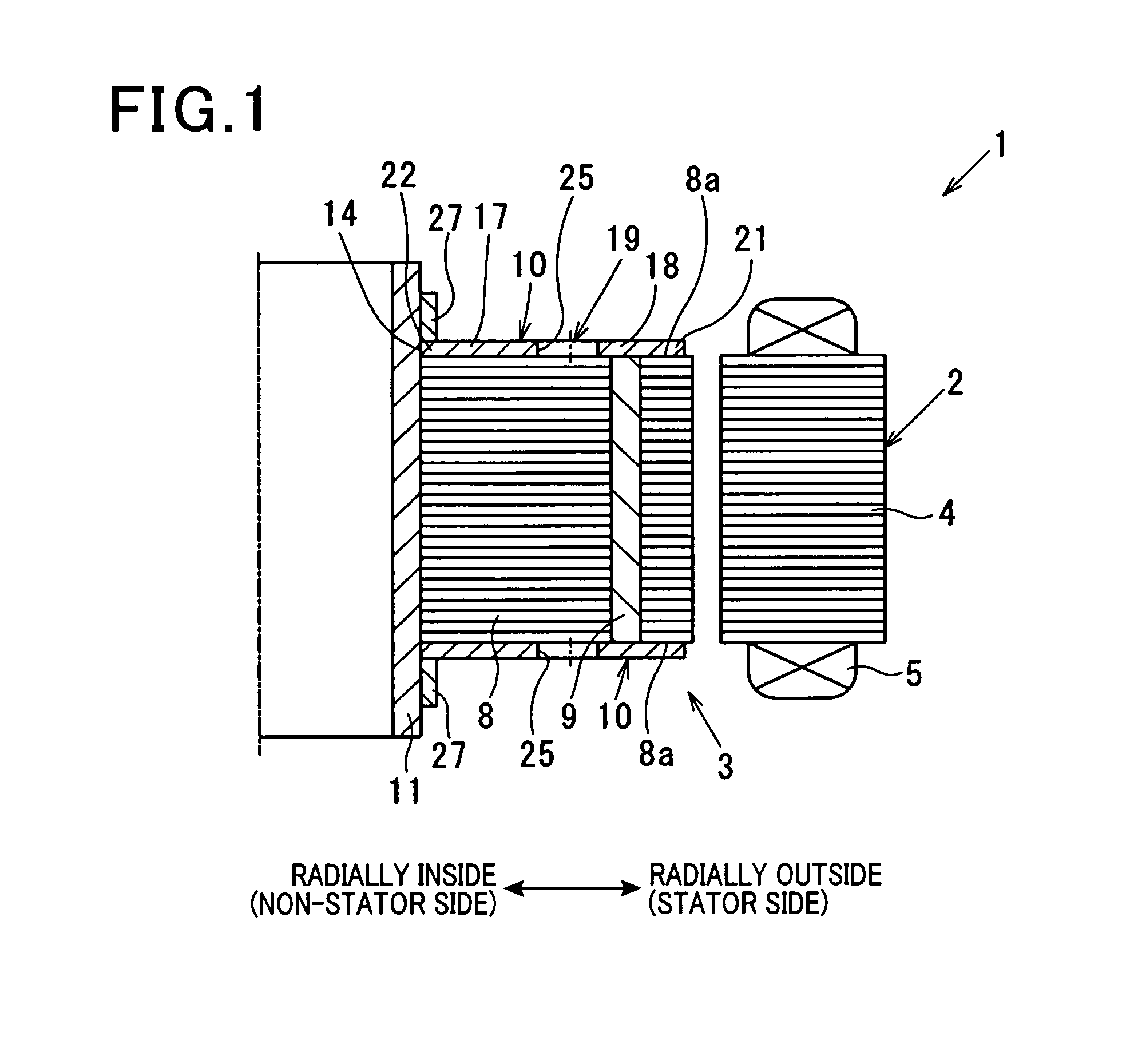
[0060]FIG. 1 shows the overall configuration of an electric rotating machine 1 which includes a rotor 3 according to a first embodiment.

[0061]In this embodiment, the electric rotating machine 1 is configured as a motor generator that can function both as an electric motor and as an electric generator in, for example, a hybrid or electric vehicle.

[0062]As shown in FIG. 1, the electric rotating machine 1 includes a hollow cylindrical stator 2 and the rotor 3 that is rotatably disposed radially inside of the stator2. That is to say, in the present embodiment, the electric rotating machine 1 is of an inner rotor type. In addition, it should be noted that for the sake of simplicity, only half of the electric rotating machine 1 is shown in FIG. 1.

[0063]The stator 2 includes a stator core 4 and a three-phase stator coil 5. The stator core 4 is formed, by laminating a plurality of magnetic steel sheets, into a hollow cylindrical shape. The stator coil 5 is mounted on the s...

second embodiment

[Second Embodiment]

[0100]This embodiment illustrates a rotor 3 which has a similar configuration to the rotor 3 according to the first embodiment; accordingly, only the differences therebetween will be described hereinafter.

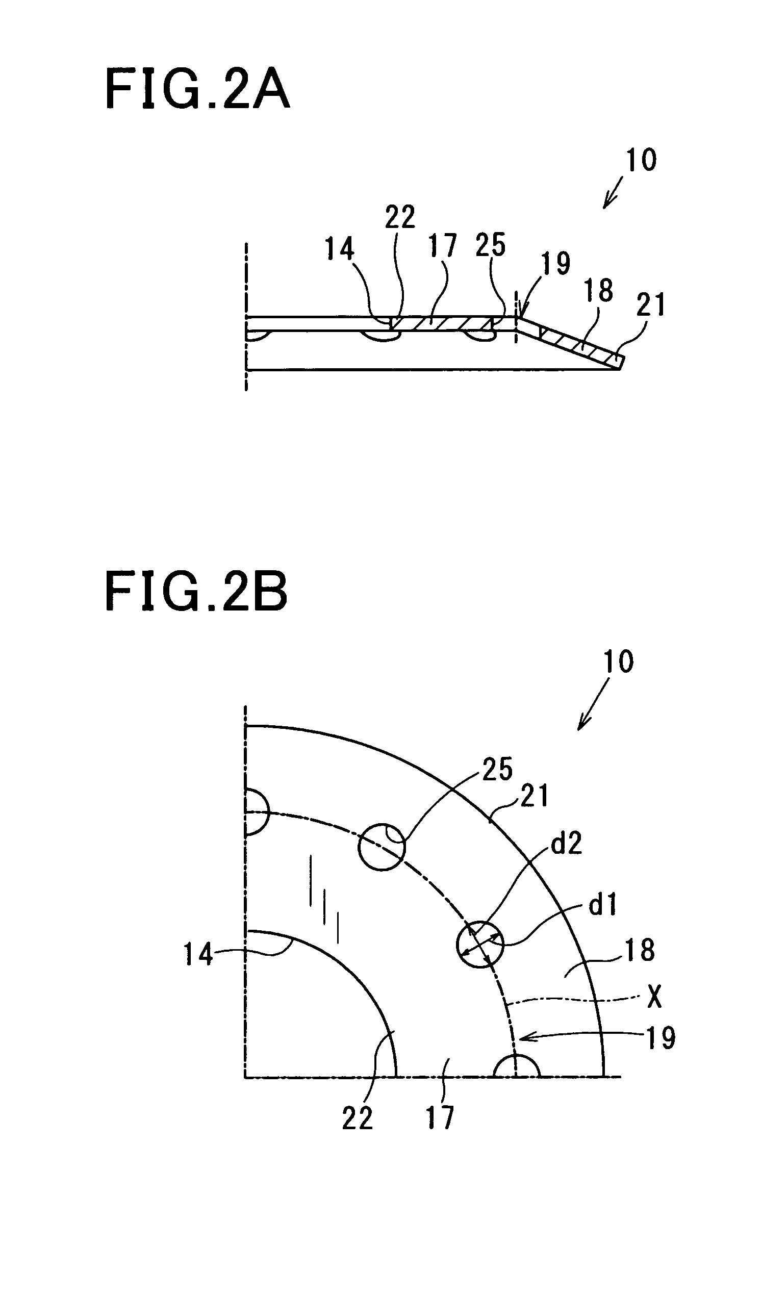
[0101]In the first embodiment, for each of the end plates 10, each of the through-holes 25 of the end plate 10 has the substantially circular shape. Moreover, all the diameters of the through-holes 25 are equal to each other (see FIG. 2B).

[0102]In comparison, in the present embodiment, as shown in FIG. 5A, for each of the end plates 10, each of the through-holes 25 of the end plate 10 also has a substantially circular shape. However, the diameters of the through-holes 25 vary according to the circumferential positions of the through-holes 25.

[0103]Specifically, in the present embodiment, the rotor 3 includes a plurality of auxiliary magnetic poles 3B in addition to the magnetic poles 3A formed by the permanent magnets 9 (to be referred to as main magnetic poles 3...

third embodiment

[Third Embodiment]

[0115]This embodiment illustrates a rotor 3 which has a similar configuration to the rotor 3 according to the first embodiment; accordingly, only the differences therebetween will be described hereinafter.

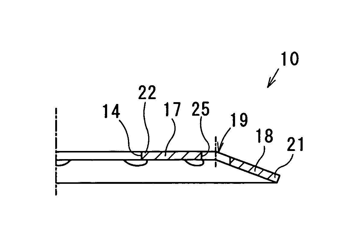
[0116]In the first embodiment, for each of the end plates 10, in the natural state of the end plate 10 before being mounted to the corresponding axial end face 8a of the rotor core 8, the proximal portion 17 of the end plate 10 extends, from the opening edges of the through-hole 14 of the end plate 10, radially outward so as to be parallel to the corresponding axial end face 8a of the rotor core 8. On the other hand, the distal portion 18 of the end plate 10 extends, on the radially outside of the proximal portion 17, radially outward so as to be inclined axially inward with respect to the corresponding axial end face 8a of the rotor core 8 (see FIG. 2A).

[0117]In comparison, in the present embodiment, as shown in FIG. 7A, for each of the end plates 10, in the natu...


PUM

PropertyMeasurementUnit
deflection stressaaaaaaaaaa
angleaaaaaaaaaa

Abstract

A rotor includes a rotor core comprised of magnetic steel sheets laminated in the axial direction and a pair of end plates that are respectively provided on the axial end faces of the rotor core so as to together sandwich the rotor core in the axial direction. The rotor is rotatably disposed in an electric rotating machine with a circumferential surface of the rotor core facing a stator. At least one of the end plates is configured to have through-holes, each of which is formed so as to axially penetrate the end plate, and a pressing portion that is radially positioned on the stator side of the through-holes. The pressing portion abuts a corresponding one of the axial end faces of the rotor core and exerts an axial load on the corresponding axial end face of the rotor core by an elastic force of the end plate.

Description

CROSS-REFERENCE TO RELATED APPLICATION[0001]This application is based on and claims priority from Japanese Patent Applications No. 2011-81589, filed on Apr. 1, 2011, and No. 2011-81563, filed on Apr. 1, 2011, the contents of which are hereby incorporated by reference in their entireties into this application.BACKGROUND[0002]1. Technical Field[0003]The present invention relates to rotors for electric rotating machines that are used in, for example, motor vehicles as electric motors and electric generators, and to methods of manufacturing the rotors. In addition, the invention can also be applied to industrial machines and household electrical appliances.[0004]2. Description of Related Art[0005]There are known rotors for electric rotating machines which include a rotor core formed by stacking a plurality of magnetic steel sheets and a pair of end plates that are respectively provided on opposite axial end faces of the rotor core so as to together sandwich the rotor core (see, for exam...

Claims


Application Information

Patent Timeline
Patent Type & Authority Patents(United States)
IPC IPC(8): H02K1/27H02K1/32
CPCH02K1/276H02K1/32H02K2213/03Y10T29/49012
Inventor TAKAHASHI, YUKIITOU, KAZUTERUITOU, YUUICHIROU
Owner DENSO CORP
Why Eureka
Try Eureka