System and method for lock detection of a phase-locked loop circuit

a phase-locked loop and lock detection technology, applied in the direction of oscillator tubes, pulse automatic control, electrical equipment, etc., can solve the problems of large footprint of complicated circuits, reduce the number of erroneous indications of pll locks, and reduce false lock indications

Inactive Publication Date: 2006-11-30
KK TOSHIBA
View PDF3 Cites 3 Cited by
  • Summary
  • Abstract
  • Description
  • Claims
  • Application Information

AI Technical Summary

Benefits of technology

[0011] A technical advantage of the invention is the ability to detect PLL lock by observation of a substantially stable digital signal. In particular, a counter is incorporated into a PLL circuit such that the counter receives input from a phase-frequency detector which compares a PLL input signal to a PLL feedback signal and provides output indicating the difference between the signals. Therefore, when a counter receiving input from a phase-frequency detector is observed to have a substantially stable value, the PLL is identified as locked.
[0012] Another advantage presented by this invention is the reduction in the number of erroneous indications of PLL lock. Observing stable counter values for a user-defined period of time may reduce such erroneous indications.
[0013] Similarly, false lock indications can be avoided by using a variable timer to obtain counter values for comparison. Sampling with a pseudo-random frequency may prevent sampling with a frequency that corresponds with a periodic PHASE-LOCKED LOOP feedback system frequency.
[0014] Yet another advantage presented by this invention is the reduction in footprint as compared to other phase-locked loop lock devices. Footprint reduction may be of particular importance for phase-locked loop circuits manufactured using CMOS technologies.
[0015] These, and other, aspects of the invention will be better appreciated and understood when considered in conjunction with the following description and the accompanying drawings. The following description, while indicating various embodiments of the invention and numerous specific details thereof, is given by way of illustration and not of limitation. Many substitutions, modifications, additions or rearrangements may be made within the scope of the invention, and the invention includes all such substitutions, modifications, additions or rearrangements.

Problems solved by technology

However, some such devices and methods may at times incorrectly indicate that a PLL has achieved lock.
In addition, such prior art locking devices and methods may require complicated circuitry to enable, and these complicated circuits may have large footprints.

Method used


Image

  • System and method for lock detection of a phase-locked loop circuit
  • System and method for lock detection of a phase-locked loop circuit
  • System and method for lock detection of a phase-locked loop circuit

Examples


Embodiment Construction

[0026] The invention and the various features and advantageous details thereof are explained more fully with reference to the nonlimiting embodiments that are illustrated in the accompanying drawings and detailed in the following description. Descriptions of well known starting materials, processing techniques, components and equipment are omitted so as not to unnecessarily obscure the invention in detail. It should be understood, however, that the detailed description and the specific examples, while indicating preferred embodiments of the invention, are given by way of illustration only and not by way of limitation. After reading the specification, various substitutions, modifications, additions and rearrangements will become apparent to those skilled in the art from this disclosure which do not depart from the scope of the appended claims.

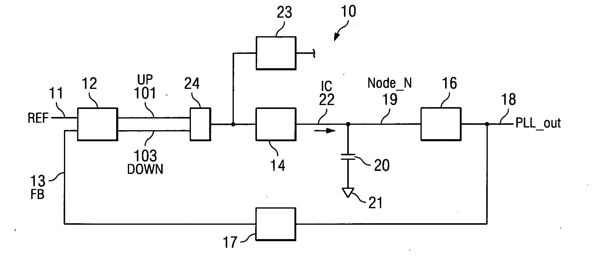
[0027]FIG. 1 is a block diagram of one embodiment of a phase-locked loop electrical circuit having a lock detector.

[0028] Phase-locked loop c...


PUM


Abstract

Systems and methods for detecting phase-locked loop circuit lock. In particular, a lock detector configured to detect PLL stability for a user-defined period of time prior to asserting a PLL-lock-detected output. Stability may be indicated by a counter inserted into a PLL circuit and arranged between a phase-frequency detector and a charge pump. Because the counter value is acted upon by the phase-frequency detector, PLL lock is indicated by counter value stability. The digital counter value may be provided to a digital charge pump and a lock detector simultaneously. The lock detector includes registers and difference detectors to determine when the difference between counter values is below a user-defined tolerance. The lock detector may include a variable timer to avoid false indications of lock which may occur when counter values are sampled with the same frequency as a fluctuation frequency of the counter value.

Description

TECHNICAL FIELD OF THE INVENTION [0001] The present invention relates to a phase-locked loop circuit, and more particularly, to detecting lock of a PLL circuit. BACKGROUND OF THE INVENTION [0002] Phase-locked loops are widely used for various applications such as in digital electronics, signal K telemetry, and communications applications. A typical PLL may include a phase-frequency detector, a charge pump, and a voltage-controlled oscillator. [0003] Phase-locked loop integrated circuits receive an input frequency signal and produce an oscillator frequency output signal. The frequency of the oscillator output signal may be a multiple of the frequency of the input signal. The PLL is said to be locked when the PLL produces an oscillator output signal which has a frequency which is a multiple of the input frequency signal within some tolerance. It is noted that a multiple of one is possible. Some applications using PLL circuits may use information regarding PLL lock. Useful information ...

Claims


Application Information

Patent Timeline
Patent Type & Authority Applications(United States)
IPC IPC(8): H03L7/06
CPCH03L7/089H03L7/0895Y10S331/02H03L2207/14H03L7/095
Inventor TAKASE, SATORU
Owner KK TOSHIBA
Why Eureka
Try Eureka