
Stabilizer platform for a camcorder

a stabilizer and camcorder technology, applied in the field of electronic devices, can solve the problems of affecting the stability of the camcorder, etc., and achieves the effects of eliminating up and down or jittery motion, facilitating steady recording, and stable suppor

Inactive Publication Date: 2006-11-30
GALE CHARLES
View PDF19 Cites 9 Cited by
  • Summary
  • Abstract
  • Description
  • Claims
  • Application Information

AI Technical Summary

Benefits of technology

[0018] It is an objective of this invention to provide a steady and stable support for a camcorder, hand held camcorder, digital hand held camcorder with still camera features or DVD digital hand held camcorder with still camera features. The support facilitates steady recording and then viewing from either the viewfinder or the liquid crystal display screen of the subject thus eliminating the up and down or jittery motion commonly encountered during video recording.
[0019] It is a further objective of this invention to provide a lightweight support, easily manufactured with minimal cost to be produced on a mass production basis.

Problems solved by technology

It is common knowledge that camcorders on the market today due to their small size have an inherent problem of producing a poor quality picture due to hand movement of the user which is not stable thus producing a shaky, unsteady and jittery picture.
Even with the stabilizing chip that is present in the camcorder body today does not remedy the jittery movements since a user will video for long periods of time and tire while doing so or walk or run while videoing thus magnifying the problem.
U.S. Pat. No. 2,370,611 to Du Mais is a bulky and complicated apparatus with interlocking members which hold a still camera and requires a strap around the arm.
This is not practical or helpful for use with the camcorders of today.
This is not suitable for long-term video taping.
This presents a heavier load in the front causing imbalance and discomfort and is not practical in use.
The use of slider plates introduces a potential for pinching or injury to the user.
U.S. Pat. No. 5,073,788 to Lingwall is a cumbersome camera apparatus which requires the use of hinges, straps, fasteners and a body harness to attach to the user for still photography.
In certain instances this device cannot be stored compactly or thinly in the camera bottom portion.
U.S. Pat. No. 5,098,182 to Brown is a complicated and cumbersome support system used to stabilize camera equipment for unwanted motions.
There are two “struts” which extend from the base support making the device difficult to hold or balance, especially due to the counterbalancing by a secondary view finding device and batteries at the bottom of the first strut.
There are finger grips on each side with which to hold the device causing the user's fingers to be cramped in a bent position to support and steady the camera.
While gripping the stabilizer, a user's hand is not free to control the basic functions of a camera such as zooming, power, and other attendant functions.
It has many attachments, struts, pivoting joints with upper yoke, straps for use which make it cumbersome and complicated, especially when the extension pole is introduced for lifting and tilting the camera over and above the user's shoulders or as use of a monopod.
This device would be uncomfortable for use especially for long periods of video taping as well as having inherent personal protection flaws for designing and suggesting this device can be placed against the face and neck.
The other advantage of this device is that twice the number of exposures can be made per second in an action sequence thus describing the still, 35 mm type camera and is not practical for video cameras.
This device will do nothing for stabilization of the picture as one would not have differing results by holding the camera with his hand.
The hand is still doing the holding for the only support with the resulting jitter and unwanted movements of the hand.

Method used


Image

  • Stabilizer platform for a camcorder
  • Stabilizer platform for a camcorder
  • Stabilizer platform for a camcorder

Examples


Embodiment Construction

[0024] According to a preferred embodiment of the present invention, an apparatus is used for the stabilization of video recording equipment. The apparatus along with attendant methods are explained in enabling detail below.

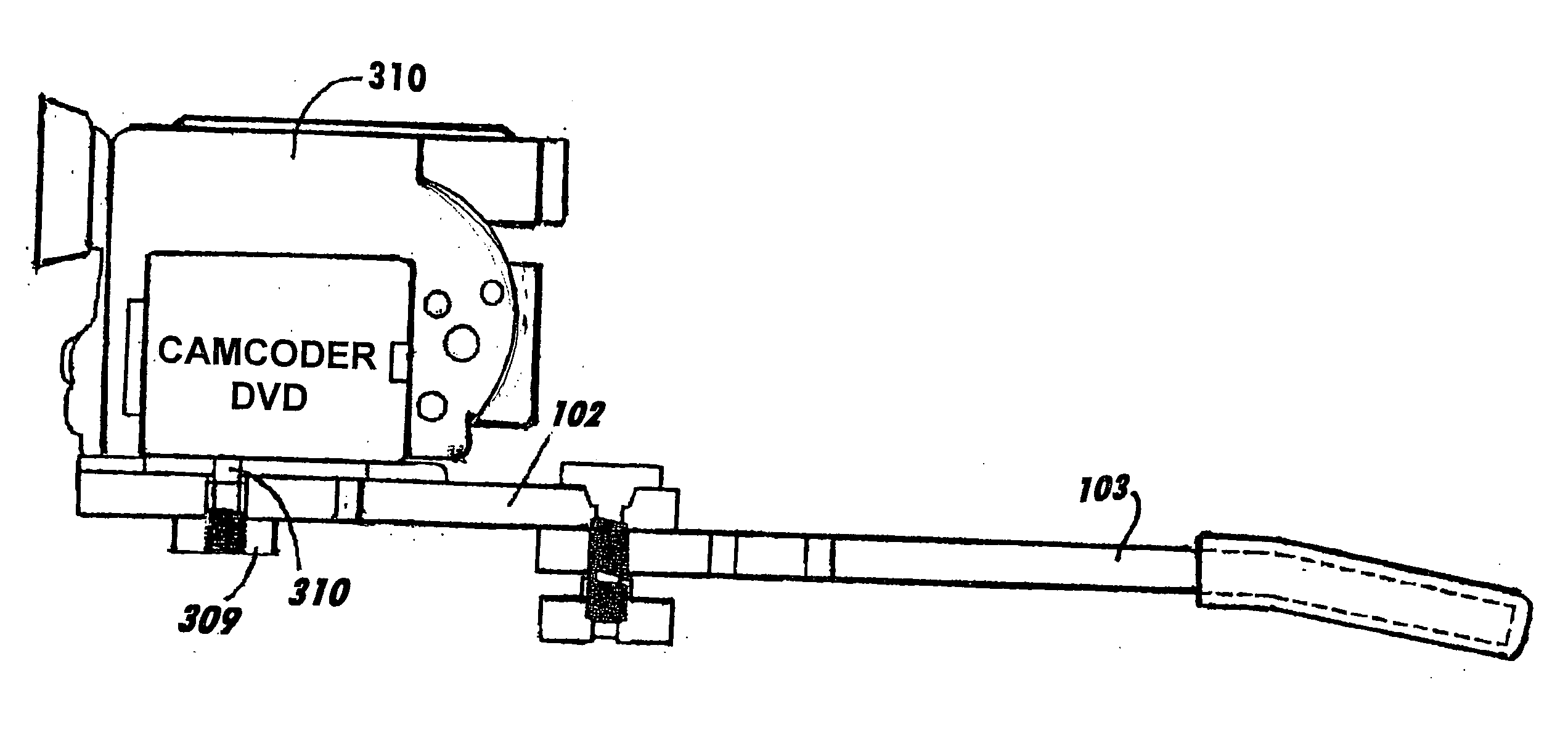
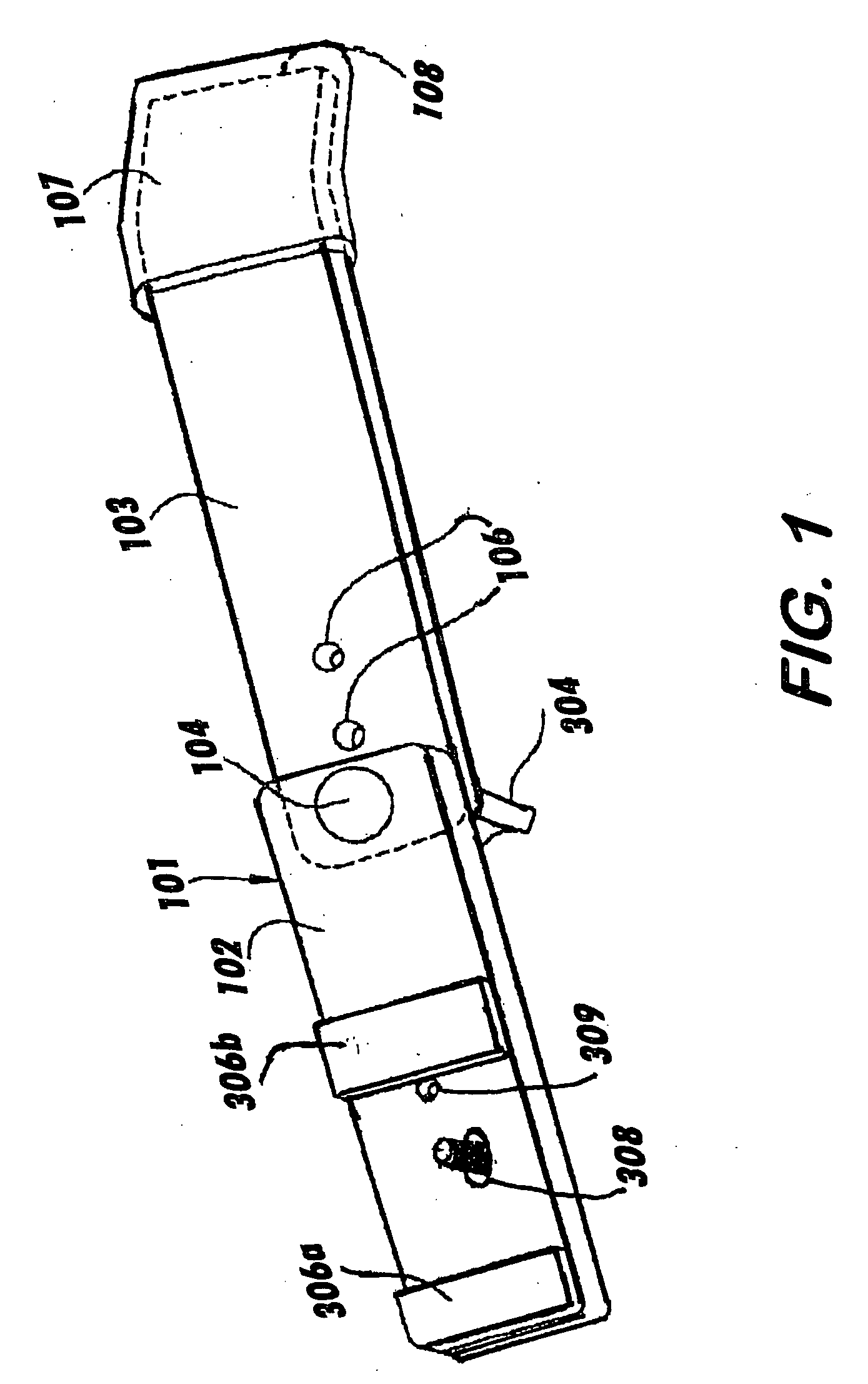
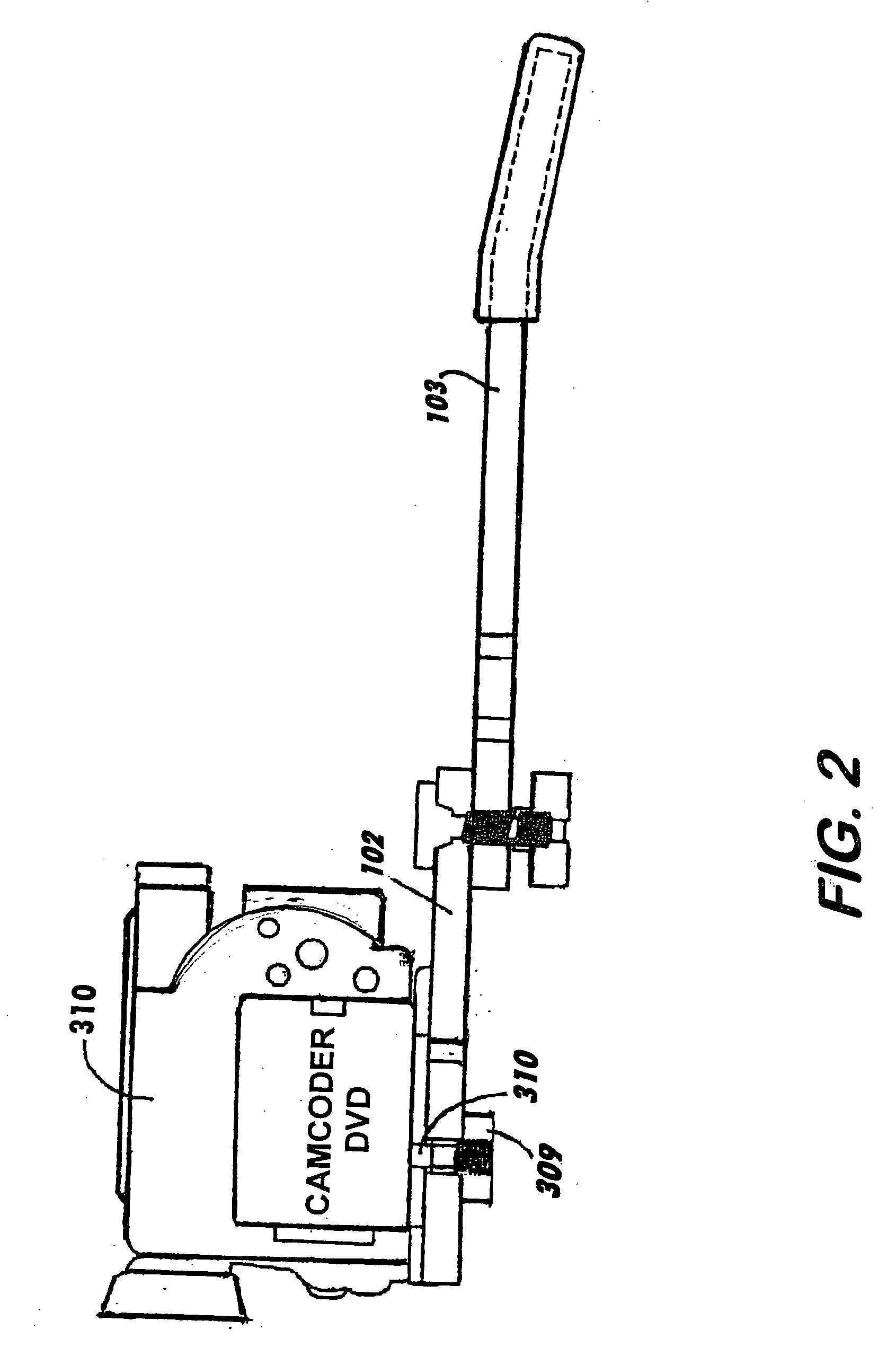
[0025]FIG. 1 is a perspective view of a preferred embodiment of the present invention. Stabilizer platform comprises a bar 101. Bar 101 comprises a first section 102 and a second section 103. First section 102 and second section 103 are rotatably connected together by a locking bolt 104, which passes through holes 301 and 106 extending through first section 102 and second section 103, respectively. Hole 106 can be one of a number of holes positioned in second section 103 so that the overall length of bar 101 in the extended position can vary, depending upon the specific user utilizing the invention. Located near camera pad 306b is a bore hole for future use 309. A foam pad 107 is positioned on an end 108 of second section 103 opposite from holes 106. Preferably ...


PUM


Abstract

A camera stabilizer comprising a platform having a first end connectable to a camera and a second end extending outwardly from the first end to rest on a shoulder of a camera operator; said first end connected to said second end with a locking bolt, said locking bolt sized to fit through both a first end hole and a second end hole, said locking bolt sized to fit with a locking knob, said locking knob being threaded to accept said locking bolt, said locking bolt to be inserted through an upper surface of said first end through said first end and through said second end hole, and said locking bolt to connect with said locking knob, said first end having a camera hole sized to fit with a camera screw threaded pin, said camera screw threaded pin sized to engageably attach to a camera for use in affixing said camera to said platform, said camera screw threaded pin to be inserted through an under surface of said first end held in place by a retaining ring to affix with camera.

Description

FIELD OF THE INVENTION [0001] The present invention is in the area of electronics and more particularly pertains to visual recording accessories. BACKGROUND OF THE INVENTION [0002] This invention relates to a stabilizing platform support for a camcorder or other visual recording devices. Said invention rests on the shoulder of a camera operator to video subject thereby eliminating up and down motion normally incurred while filming. [0003] It is common knowledge that camcorders on the market today due to their small size have an inherent problem of producing a poor quality picture due to hand movement of the user which is not stable thus producing a shaky, unsteady and jittery picture. Even with the stabilizing chip that is present in the camcorder body today does not remedy the jittery movements since a user will video for long periods of time and tire while doing so or walk or run while videoing thus magnifying the problem. [0004] Prior attempts have been made to eliminate the unwa...

Claims


Application Information

Patent Timeline
Patent Type & Authority Applications(United States)
IPC IPC(8): H04N5/225
CPCH04N5/2251G03B17/561
Inventor GALE, CHARLES
Owner GALE CHARLES
Learn More