Exhaust filter module with mechanically positionable scan probe

Active Publication Date: 2006-12-07
CAMFIL USA
View PDF7 Cites 51 Cited by
  • Summary
  • Abstract
  • Description
  • Claims
  • Application Information

AI Technical Summary

Benefits of technology

[0009] In another embodiment, a filter module includes a housing configured to extend into an interstitial space behind a structure bounding a work area, and a mechanically positionable test probe disposed in the housing. A sample probe suitable for leak testing a filter element is disposed in the interior volume of the housing. The position of the sample probe may be co

Problems solved by technology

This requirement is problematic when the space available downstream of the filter is limited, as positioning a probe during testing may become difficult, if not impossible, to perform.
For example, in a filtered exhaust application, the interstitial space defined between a housing and a filter disposed therein can often not be readily accessed by a technician.
This manner of testing is controversial, as many believe that some pin hole filter leaks are flow dir

Method used


Image

  • Exhaust filter module with mechanically positionable scan probe
  • Exhaust filter module with mechanically positionable scan probe
  • Exhaust filter module with mechanically positionable scan probe

Examples


Embodiment Construction

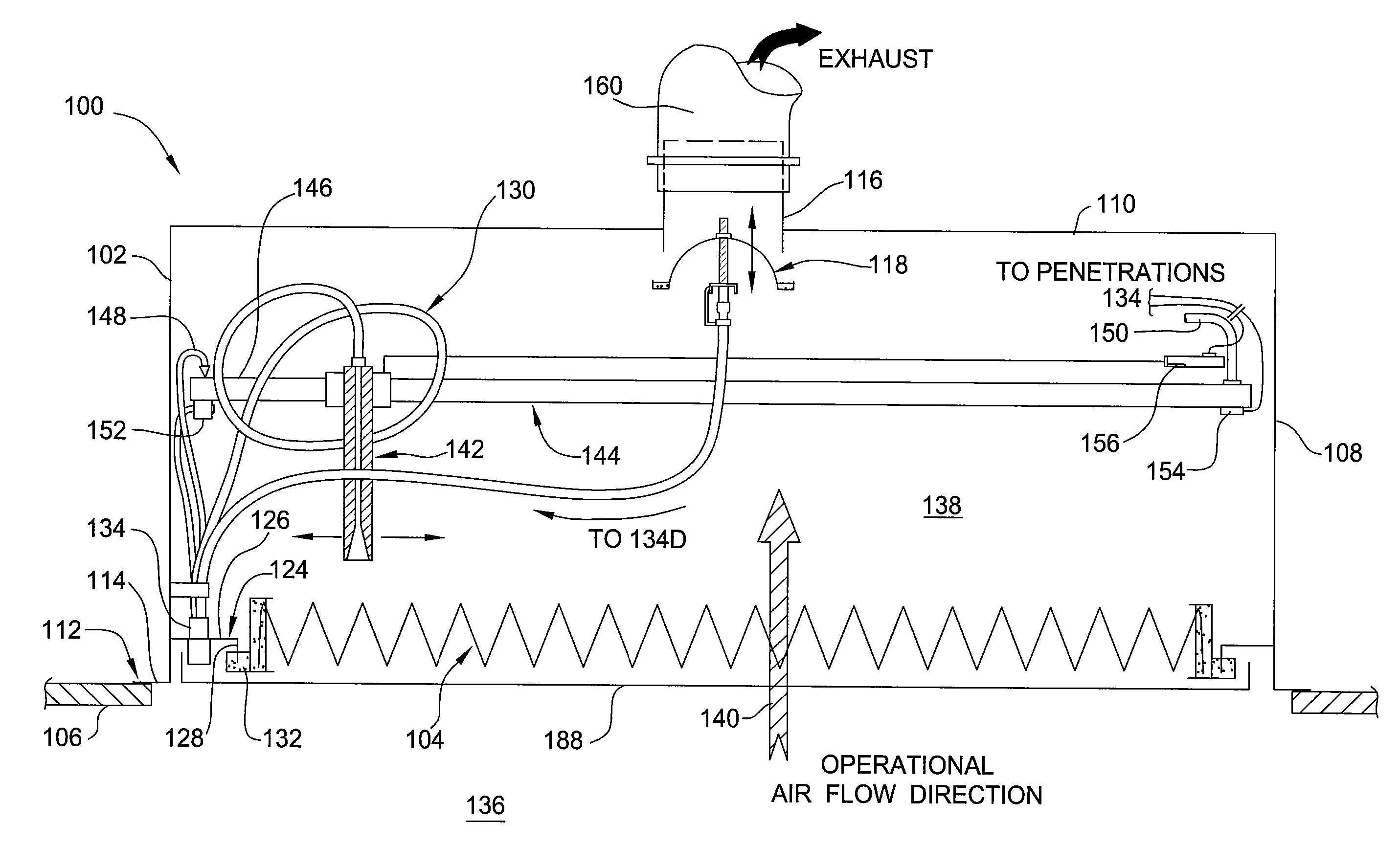
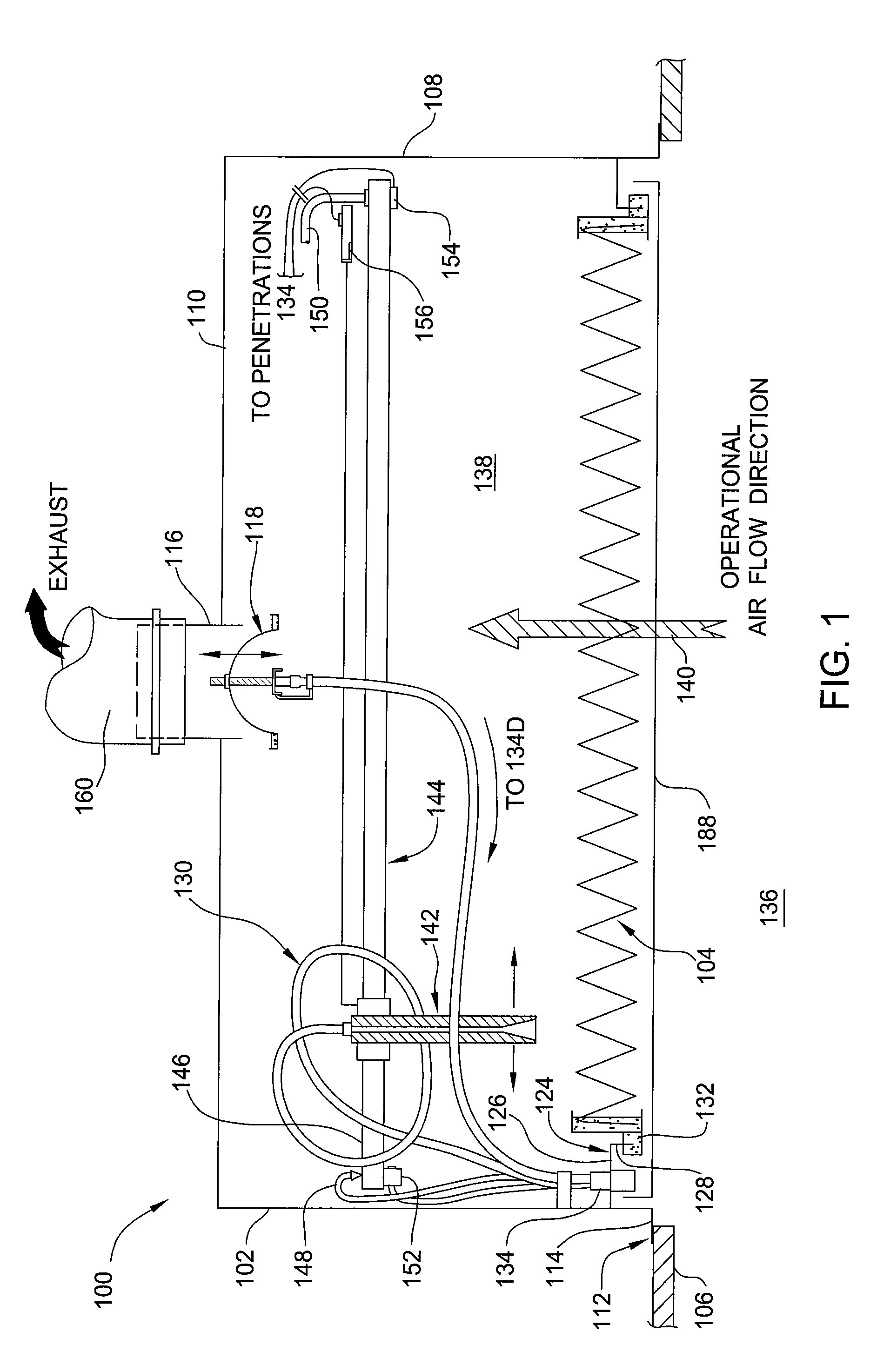
[0023]FIG. 1 is a filter module 100 having an integrated autoscan mechanism 130. Although the filter module 100 depicted in FIG. 1 is configured as a filtered exhaust for a cleanroom application, the autoscan mechanism described herein may be beneficially configured to benefit other filter housings, such as panels and diffusers used in exhaust applications. It is intended that the term “cleanroom” may refer to any laboratory, machine enclosure, room or space serviced by the filter module 100. It is intended that the term “structure” may refer to any wall, ceiling, panel or floor of the cleanroom. It is intended that the term “interstitial space” refer to the area on the other side of the structure in which the filter module is mounted that is not in the cleanroom serviced by the filter module.

[0024] The filter module 100 generally includes a housing or hood 102 which sealingly mounts a filter element or filter 104 to a structure, such as a ceiling 106 of a cleanroom, such that a fa...


PUM

PropertyMeasurementUnit
Areaaaaaaaaaaa
Flow rateaaaaaaaaaa

Abstract

Embodiments of the invention generally provide a filter module having a mechanically positionable test probe disposed therein and a method for testing a filter. In one embodiment, a filter module includes a housing adapted to receive a filter element. A sample probe suitable for leak testing the filter element is disposed in the interior volume of the housing. The sample probe may be moved to scan the filter by an actuator. In another embodiment, a method for testing a filter includes challenging a room side of a filter element disposed in a housing with a test aerosol, moving a probe disposed within the housing to obtain samples for testing and determining if the samples exceed a predefined leak criteria.

Description

BACKGROUND OF THE INVENTION [0001] This application claims benefit of U.S. Provisional Application No. 60 / 675,678, filed Apr. 28, 2005, which is hereby incorporated by reference in its entirety. This application is also related to U.S. application Ser. No. 11 / 380,737, filed Apr. 28, 2006, entitled “INTEGRATED CONTAINMENT SYSTEM” (CMFL / 044) which is hereby incorporated by reference in its entirety.BACKGROUND OF THE INVENTION [0002] 1. Field of the Invention [0003] The invention generally relates to a filter module having a mechanically-positionable test probe. [0004] 2. Description of the Related Art [0005] In many cleanroom applications, filters are often required to be scan-tested for leaks after installation. This requirement is problematic when the space available downstream of the filter is limited, as positioning a probe during testing may become difficult, if not impossible, to perform. Examples of such applications where access to the downstream side of the filter is limited,...

Claims


Application Information

Patent Timeline
IPC IPC(8): B01D45/00
CPCB01D46/0086B01D46/10B01D46/42B01D2273/18B01D46/521B01D2271/02B01D46/444
Inventor MORSE, THOMAS C.HUZA, MARK
Owner CAMFIL USA
Why Eureka
Try Eureka