Therapeutic foot/leg/knee elevation

Inactive Publication Date: 2006-12-07
FOGGIO JOE +1
View PDF18 Cites 20 Cited by
  • Summary
  • Abstract
  • Description
  • Claims
  • Application Information

AI Technical Summary

Benefits of technology

[0008] In an embodiment, the adjustable limb support device includes a front and rear lifts each being of scissors-like

Problems solved by technology

Embodiments of existing devices are generally cumbersome to use, difficult to adjust and/or require mounting to the bed frame.
In such devices, nurses perform the adjustment because patients are generally unable to adjust the height themselves.
Such devices permit the limb support platform to be raised or lowered but fail to provide m

Method used


Image

  • Therapeutic foot/leg/knee elevation
  • Therapeutic foot/leg/knee elevation
  • Therapeutic foot/leg/knee elevation

Examples


Embodiment Construction

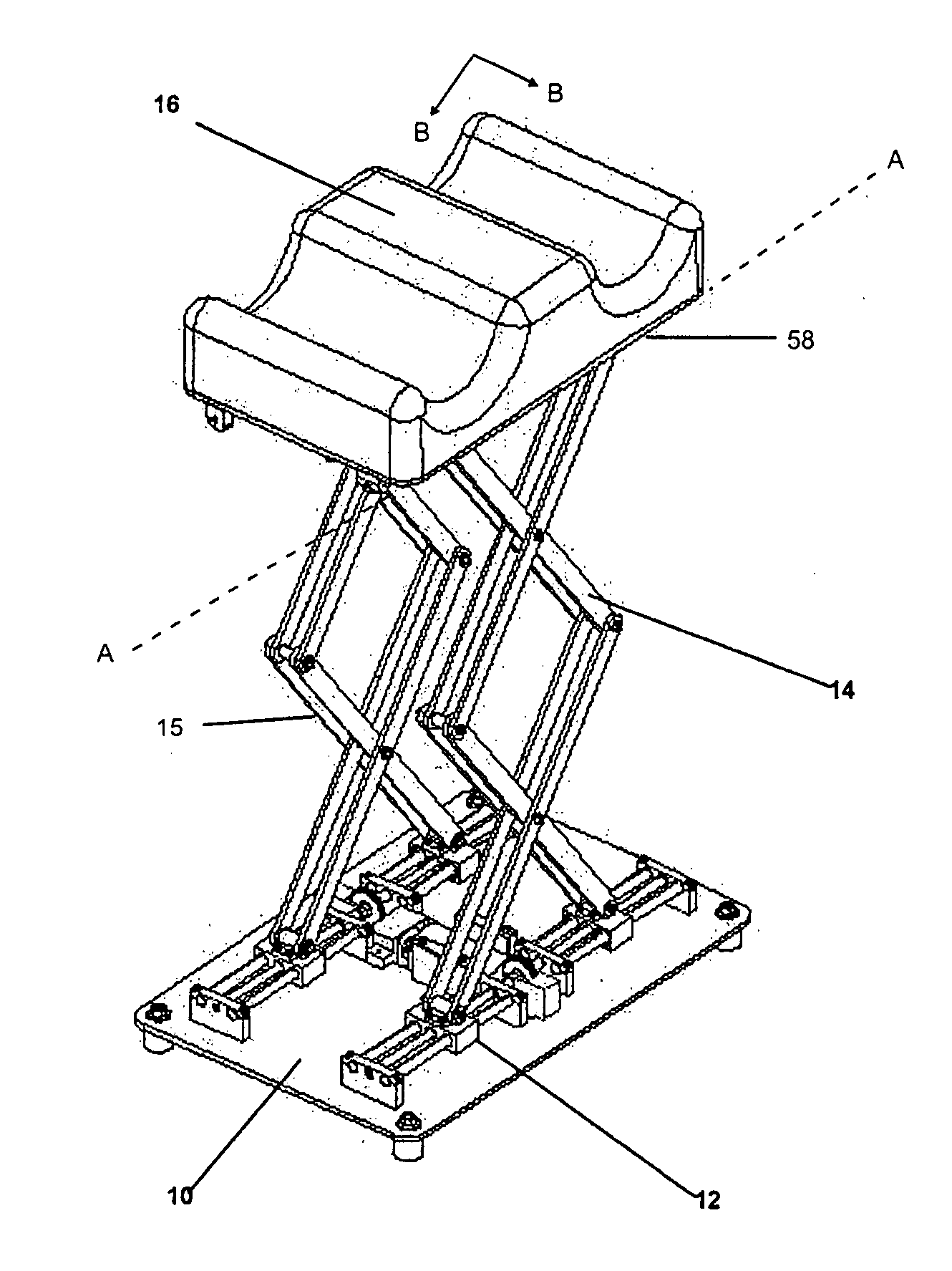
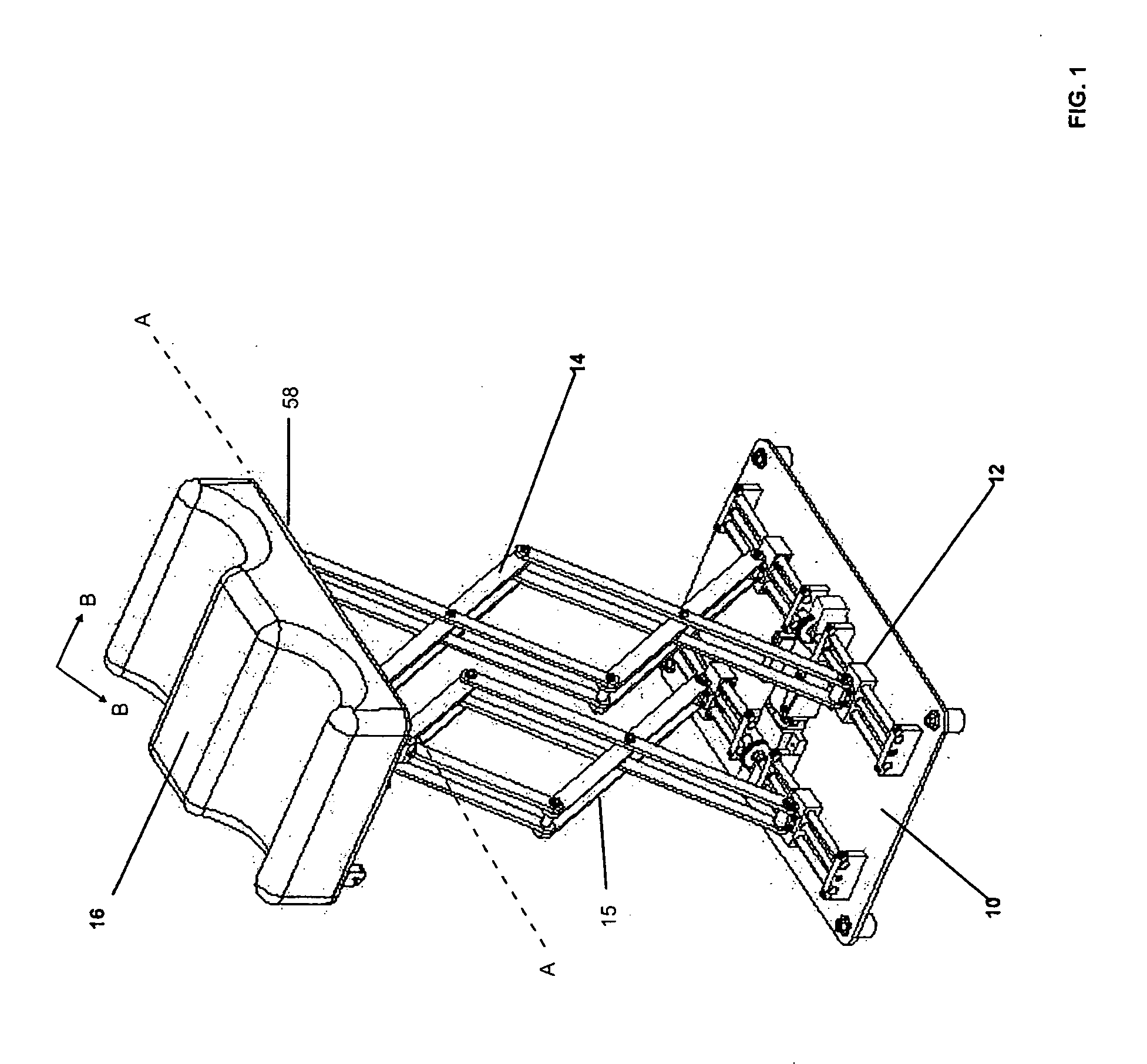
[0024] Referring to FIG. 1 an embodiment of the adjustable limb support device of the present application is shown. In an embodiment, the adjustable limb support device includes a drive mechanism 12 mounted to a base 10. The drive mechanism 12 is adapted to drive a front lift 14 and a rear lift 15, whereby the front and rear lifts 14, 15 may be driven concurrently or independently. As such, the front and rear lifts 14, 15 are adapted to raise and lower a top plate 58 and limb support platform 16. The front and rear lifts 14, 15 can also be driven independently such that the top plate 58 is permitted to rotate about a pivot axis A-A, thereby causing the top plate 58 and limb support platform 16 to be tilted off a horizontal plane B-B.

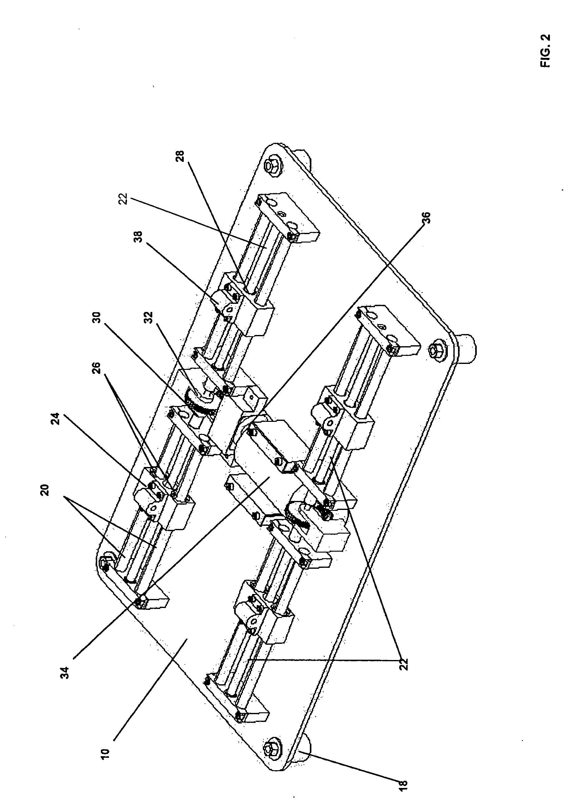
[0025] Referring also to FIG. 2. The base 10 may include elastomer feet 18 to increase its stability when placed on a floor or on a bed. The drive mechanism 12 includes of linear bearing shafts 20, left hand and right hand lead screws 22 and linear slid...


PUM


Abstract

An adjustable limb support device comprising a front lift and a rear lift, each disposed substantially beneath a top plate. A drive mechanism adapted to drive the front and rear lifts both concurrently and independently, thereby permitting the elevation of the top plate to be raised or lowered and permitting the top plate to tilt off a horizontal plane.

Description

RELATED APPLICATION [0001] This application claims the benefit of the filing date of co-pending U.S. provisional patent application No. 60 / 684,882, filed on May 26, 2005.BACKGROUND OF THE INVENTION [0002] The present invention relates generally to adjustable limb support devices, and more particularly to adjustable limb support devices having motorized elevation and tilt capabilities. [0003] It is often desirable to elevate the legs of a patient recovering from injuries or illnesses such as strokes, surgeries, or broken bones. As such, adjustable limb support devices are well known in the art. Embodiments of existing devices are generally cumbersome to use, difficult to adjust and / or require mounting to the bed frame. For example, previous embodiments may require manual operation when height adjustment is needed. In such devices, nurses perform the adjustment because patients are generally unable to adjust the height themselves. [0004] It is also known in the art to combine an adjus...

Claims


Application Information

Patent Timeline
IPC IPC(8): E06C1/00
CPCA47C16/025
Inventor FOGGIO, JOEMOISE, VLAD
Owner FOGGIO JOE
Why Eureka
Try Eureka