Optical wavelength and power measurement device

a technology of optical power measurement and optical wavelength, which is applied in the field can solve the problems of large volume and high power consumption, inability to use osa in an external environment, and high cost of equipment thereof, so as to achieve the effect of reducing the size of optical wavelength and optical power measurement devices, easy selection, and convenient mass production

Inactive Publication Date: 2017-09-19
ELECTRONICS & TELECOMM RES INST
View PDF19 Cites 0 Cited by
  • Summary
  • Abstract
  • Description
  • Claims
  • Application Information

AI Technical Summary

Benefits of technology

[0019]The present invention has been made in an effort to provide an optical wavelength and optical power measurement device having an inexpensive price and maximized portability, for measuring an optical wavelength and optical power, and having an inspection function of a ferrule cross-section of an optical connector.
[0031]Further, by forming a sensing unit by combining one or more motors, and DWDM wavelength filters are mounted in parallel, a size of an optical wavelength and optical power measurement device can be reduced.
[0032]Further, by counting a signal of light by sequentially mounting a plurality of DWDM wavelength filters at equal intervals, a DWDM wavelength filter having the same wavelength as that of an input communication light source of an infrared ray wavelength region is selected and thus an input wavelength can be easily selected.
[0033]Further, through simplification of the above structure, mass production can be easily performed and an optical wavelength and optical power measurement device can be produced with an inexpensive price.

Problems solved by technology

Currently, a method of using rotated grating is generally used, but equipment thereof is expensive and is weak with respect to vibration.
Equipment that measures such an optical wavelength requires elaborate optical technology and a complex process, and thus the equipment has a drawback in that it has a large volume and high power consumption and that is weak against impact.
Upon installation and maintenance of an optical subscriber network to be performed in the future, when simply measuring only optical power, there are several difficulties.
The OSA is very expensive equipment at about 10,000-50,000 US dollars, and thus when configuring a network, the OSA may not be used in an external environment.
As described above, for maintenance of a rapidly increasing DWDM optical communication system and transmission line, demand for a portable DWDM optical wavelength and optical power measurement device increases, but a conventional optical wavelength and optical power measurement device has only an optical wavelength and optical power measuring function, so when knowing a wavelength to measure, the conventional optical wavelength and optical power measurement device may measure accurate optical power, but it is difficult to produce a portable optical measurement device having a ferrule cross-section inspection function of an optical connector in the field in view of an existing DWDM wavelength filter module structure.

Method used


Image

  • Optical wavelength and power measurement device
  • Optical wavelength and power measurement device
  • Optical wavelength and power measurement device

Examples


Embodiment Construction

[0040]The present invention will be described more fully hereinafter with reference to the accompanying drawings, in which exemplary embodiments of the invention are shown. As those skilled in the art would realize, the described embodiments may be modified in various different ways, all without departing from the spirit or scope of the present invention.

[0041]The drawings and description are to be regarded as illustrative in nature and not restrictive, and like reference numerals designate like elements throughout the specification.

[0042]Further, in the drawings, a size and thickness of each element are arbitrarily represented for better understanding and ease of description, and the present invention is not limited thereto.

[0043]In addition, unless explicitly described to the contrary, the word “comprise” and variations such as “comprises” or “comprising” will be understood to imply the inclusion of stated elements but not the exclusion of any other elements.

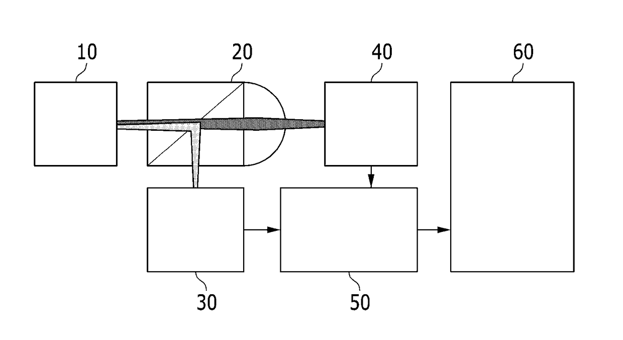
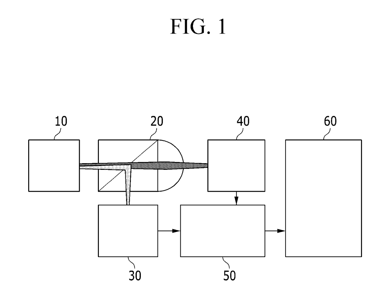
[0044]FIG. 1 is a diag...


PUM


Abstract

An optical wavelength and optical power measurement device is provided. The optical wavelength and optical power measurement device includes: an input unit in which an optical connector that emits communication light of an infrared ray wavelength region is connected; a filter unit that separates the communication light of an infrared ray wavelength region and light of a visible ray wavelength region; a sensing unit that communicates with a path of the communication light of an infrared ray wavelength region of the filter unit and in which a signal of the communication light of an infrared ray wavelength region is input; and an inspection unit that communicates with a path of the light of the visible ray wavelength region of the filter unit and that inspects a surface of the optical connector.

Description

CROSS-REFERENCE TO RELATED APPLICATION[0001]This application claims priority to and the benefit of Korean Patent Application No. 10-2014-0166877 filed in the Korean Intellectual Property Office on Nov. 26, 2014, the entire contents of which are incorporated herein by reference.BACKGROUND OF THE INVENTION[0002](a) Field of the Invention[0003]The present invention relates to an optical wavelength and optical power measurement device. More particularly, the present invention relates to an optical wavelength and optical power measurement device using a sensing unit that is formed with a Dense Wavelength Division Multiplexing (DWDM) wavelength filter and a micro motor.[0004](b) Description of the Related Art[0005]Nowadays, due to development of high speed Internet and increase of Internet traffic, transmitting capacity is being continuously increased. In order to satisfy the rapidly increasing transmitting capacity, by replacing old equipment with the latest equipment, Internet service p...

Claims


Application Information

Patent Timeline
Patent Type & Authority Patents(United States)
IPC IPC(8): G01J1/04H04B10/079
CPCH04B10/07957H04B10/07955
Inventor PARK, HYOUNGJUNLIM, KWON-SEOBKANG, HYUN SEOKOH, JAISANGKIM, KEO-SIKKIM, YOUNG SUNKIM, JEONG EUNRYU, JI HYOUNGJEON, EUN KYOUNG
Owner ELECTRONICS & TELECOMM RES INST
Why Eureka
Try Eureka