
ATM repeater using hardware implemented transfer destination searching to reduce processor load

a repeater and destination technology, applied in the field of atm repeaters, can solve the problems of increasing the cost of the repeater, limiting the transfer speed of hop-by-hop transfer, etc., and achieve the effect of shortening the tim

Inactive Publication Date: 2003-06-17
KK TOSHIBA
View PDF8 Cites 22 Cited by
  • Summary
  • Abstract
  • Description
  • Claims
  • Application Information

AI Technical Summary

Benefits of technology

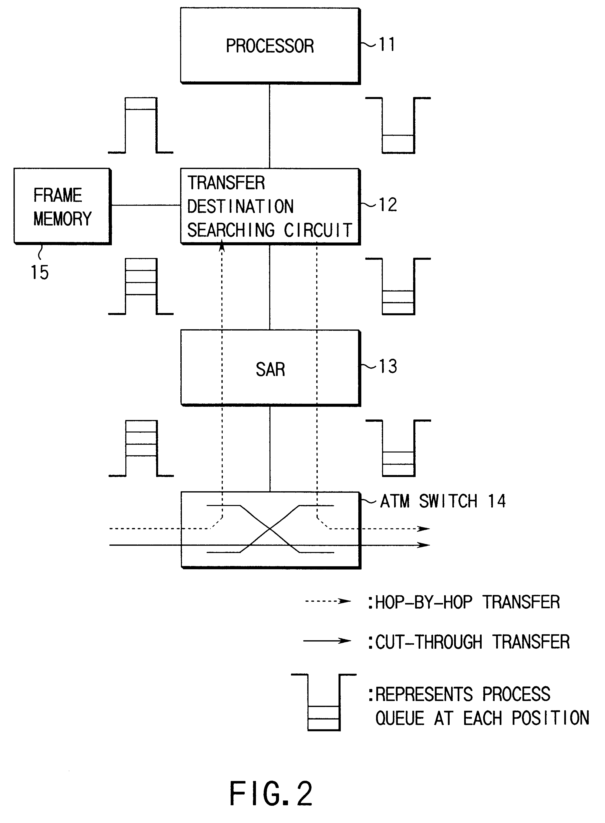
According to the present invention, the processes of extracting the header information concerning the hop-by-hop transfer and searching for the transfer destination are executed by the hardware processing. For this reason, acceleration of the hop-by-hop transfer can be implemented as compared with a conventional repeater which allows the processes to be executed by the software processing, and the price of the repeater can be lowered since a high-speed processor does not need to be prepared.
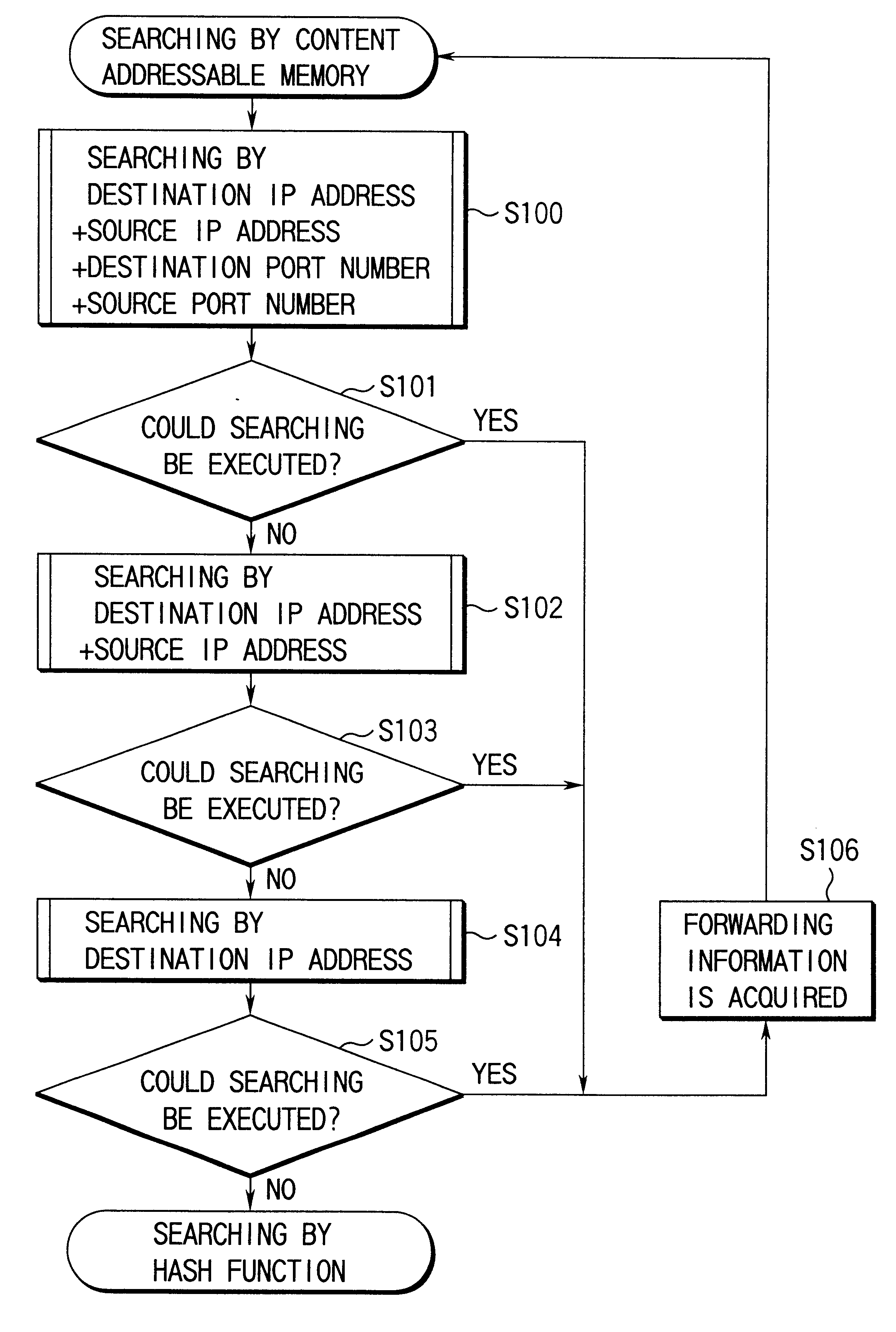
With this constitution, when the transfer destination concerning the hop-by-hop transfer is not searched by the hardware processing employing the transfer destination searching circuit, searching the transfer destination is executed with the software processing of the processor. That is, processes of extracting the header information concerning the hop-by-hop transfer and searching for the transfer destination are executed by cooperation of the hardware processing of the transfer destination searching circuit and the software processing of the processor. For this reason, for example, if the transfer destination information concerning the communications of a comparatively higher frequency is registered in advance in the transfer destination searching circuit and the transfer destination information concerning the communications of a comparatively lower frequency is registered in advance in the processor, the packet concerning the communications of a comparatively higher frequency at a general time can be transferred at a high speed by the hardware processing of the transfer destination searching circuit, and the packet which rarely arrives, i.e. which concerns the communications of a comparatively lower frequency can be transferred by the software processing of the processor. As a result, the transfer destination information corresponding to all the header information items do not need to be registered in advance in the transfer destination searching circuit and thereby the capacity of the content addressable memory in the transfer destination searching circuit can be reduced.
With this operation, the following advantages can be achieved. That is, generally, the content addressable memory has small memory capacity and expensive though its operating speed is high. On the other hand, an SRAM or DRAM, which is comparatively cheap and has a large capacity, is used as the compression searching memory. Therefore, by allowing the content addressable memory to store not the transfer destination information of all the communications that are to be processed by the hop-by-hop transfer, but the only transfer destination information concerning some communications of a particularly higher communication frequency, and by allowing the compression searching memory to store the other information items, the memory capacity of the content addressable memory can be reduced and thereby the price of the repeater can be set to be cheap.
With this structure, in the communications of a higher frequency, the packet can be transferred by searching for the transfer destination more certainly in a shorter time in accordance with many information items in the header information.

Problems solved by technology

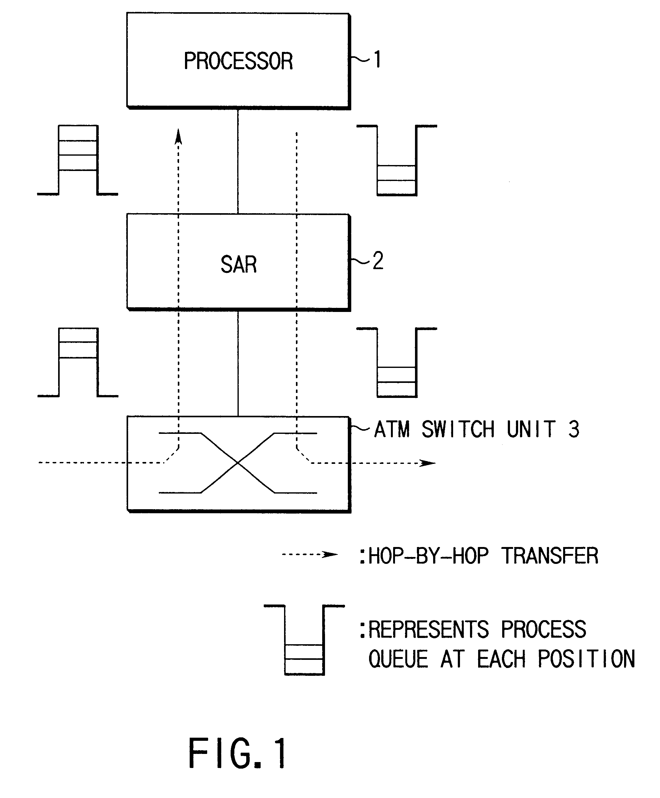
For this reason, there is a problem that load is applied to the processor 1 and the transfer speed of the hop-by-hop transfer is thereby limited by performance of the processor 1.
If this is used, the cost of the repeater is increased since the processor 1 is expensive, which is very undesirable.

Method used


Image

  • ATM repeater using hardware implemented transfer destination searching to reduce processor load
  • ATM repeater using hardware implemented transfer destination searching to reduce processor load
  • ATM repeater using hardware implemented transfer destination searching to reduce processor load

Examples


Embodiment Construction

The present invention will be described in detail with reference to the attached drawings.

FIG. 2 is a circuit block diagram showing a embodiment of an ATM repeater according to the present invention.

The ATM repeater of the present embodiment comprises a processor 11, a cell assembly / disassembly unit (SAR) 13, an ATM switch 14 and a frame memory 15, and also a transfer destination searching circuit 12. The transfer destination searching circuit 12, arranged entirely by the hardware, is constituted by a content addressable memory 21, an HASH searching pointer table 22, a forwarding table 23 and a search control unit 24 as shown in FIG. 3.

The header information and the pointer information concerning communications of a comparatively high frequency of communication are stored in advance in the content addressable memory 21. FIG. 4 shows an example of the stored information. Destination IP addresses, source IP addresses, destination port numbers and source port numbers, which constitute ...


PUM


Abstract

The present invention aims at implementing acceleration of the hop-by-hop transfer without using a high-speed processor. In the present invention, a transfer destination searching circuit (12) constituted by hardware is provided in addition to a processor (11). In the transfer destination searching circuit (12), after header information has been extracted from received IP packet data, a content addressable memory (21) is first searched by using the header information as a key. If corresponding forwarding information cannot be obtained from the searching of the content addressable memory (21), HASH function searching is executed by employing an HASH searching pointer table (22). If the forwarding information is obtained from a forwarding table (23) as a result of these searching operations, the hop-by-hop transfer of the IP packet data is executed in accordance with the forwarding information.

Description

The present invention relates to a repeater provided to execute packet routing process in, for example, a computer network or LAN, and more particularly to an ATM repeater using particularly an ATM switch.A repeater generally called a router has the hop-by-hop transfer mode as one of packet routing modes. The hop-by-hop transfer mode is a mode of extracting a destination IP address and control information from the input IP packet data, determining the transfer destination in accordance with the extracted destination IP address and control information, and transmitting the IP packet data in a line corresponding to the transfer destination, in a network layer. This process is conventionally implemented by the software process with a processor.In an ATM repeater, for example, a processor which is a microcomputer is provided to execute the address searching process for the hop-by-hop transfer. FIG. 1 is a circuit block diagram showing a schematic configuration of a conventional ATM repe...

Claims


Application Information

Patent Timeline
Patent Type & Authority Patents(United States)
IPC IPC(8): H04L12/56H04Q11/04H04L29/06H04Q3/00H04L45/74H04L47/43
CPCH04L45/00H04L45/10H04L45/742H04L45/745H04L49/309H04Q11/0478H04L45/7453H04L69/16H04L2012/562H04L2012/5667
Inventor IKEDA, KATSUHIKONOGAMI, KAZUO
Owner KK TOSHIBA
Learn More