Data output control apparatus

a control apparatus and data technology, applied in the direction of digital output to print units, instruments, wireless communication, etc., can solve the problems of hardly achieving an information service which is fully satisfactory for the user, hardly allowing information to be readily obtained anywhere, and using a fixed device, etc., to achieve the details of the network, reduce the cost of settling the service charge, and facilitate the processing of output data

Inactive Publication Date: 2008-05-27
SEIKO EPSON CORP
View PDF12 Cites 20 Cited by
  • Summary
  • Abstract
  • Description
  • Claims
  • Application Information

AI Technical Summary

Benefits of technology

[0013]The selecting means 11 may be implemented in any form as long as it allows selection of one of the plurality of output terminals 21. More specifically, it selects an output terminal 21 which is presumably the most suitable for the user of the portable terminal 20 to receive the service of output data. In this case, the output terminal which is presumably the most suitable for the user of the portable terminal 20 to receive the service of output data is, for example, an output terminal 21 which is presumably nearest, in terms of distance or time, with reference to the position of the portable terminal 20, an output terminal 21 which is presumably nearest, in terms of distance or time, to a destination of the user of the portable terminal 20, an output terminal which allows the user to receive the service of output data quickest in time with considerations to the data output rates of the output terminals 21, or an output terminal 21 which provides the service of output data at a cheapest price.
[0049]Furthermore, in accordance with the data output control apparatus according to claims 8 of the present invention, until the sum of the total communications time in accordance with the service charge and the actual total communications time exceeds a predetermined time, the user is charged with only a fixed charge, saving payment of the service charge until the actual communications time of the portable terminal exceeds the predetermined time. Accordingly, the service provider also receives the advantage that an even more satisfactory information service can be provided to the user.

Problems solved by technology

However, although such a portable terminal allows information on the Internet to be readily obtained anywhere, because the construction of display means is simplified for purposes such as reducing the size of and saving energy for the portable terminal, the displayed information is rather simplified compared with a display on an ordinary personal computer, hardly achieving an information service which is fully satisfactory for the user.
However, the arrangement using the combination of portable terminal and printing apparatus faces several technical problems which must be solved.
However, use of a fixed, particular printing apparatus would hardly allow information to be readily obtained anywhere.
The former is not feasible because it is technically very hard to achieve at this stage.
The latter is not feasible either because each printing apparatus requires a unique driver, thus requiring that the portable terminal be embedded with drivers for each of the printing apparatuses to be used.
However, when the number of prints is large, manual counting would take energy and time, and also tend to cause miscounts.
In case of a miscount, it is impossible to specifically notify the user of the service charge.
Meanwhile, in an arrangement in which counters which count the number of prints is provided in printing apparatuses in order to count the number of prints, each of the printing apparatuses needs to be provided with a counter, incurring an increased cost.
Furthermore, in accordance with such a payment method, in order to receive the printed materials, the user needs to carry enough money to pay the service charge; if the user does not carry enough money, the user is not allowed to receive the printed materials, hardly allowing information to be readily obtained anywhere.

Method used


Image

  • Data output control apparatus
  • Data output control apparatus
  • Data output control apparatus

Examples


Embodiment Construction

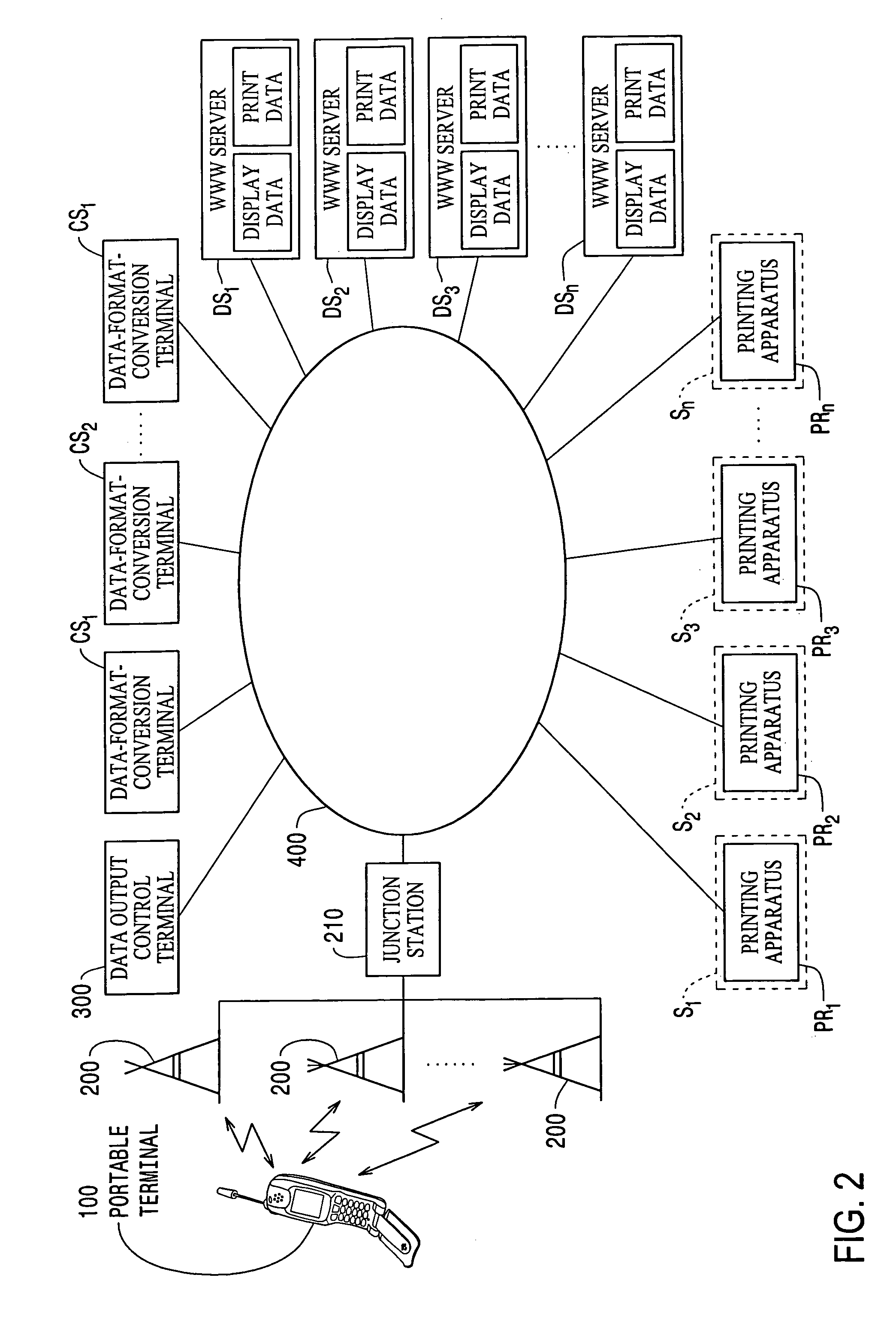
[0057]An embodiment of the present invention will be described below with reference to the drawings. FIG. 2 to FIG. 7 are diagrams showing a data output control apparatus according to the embodiment of the present invention.

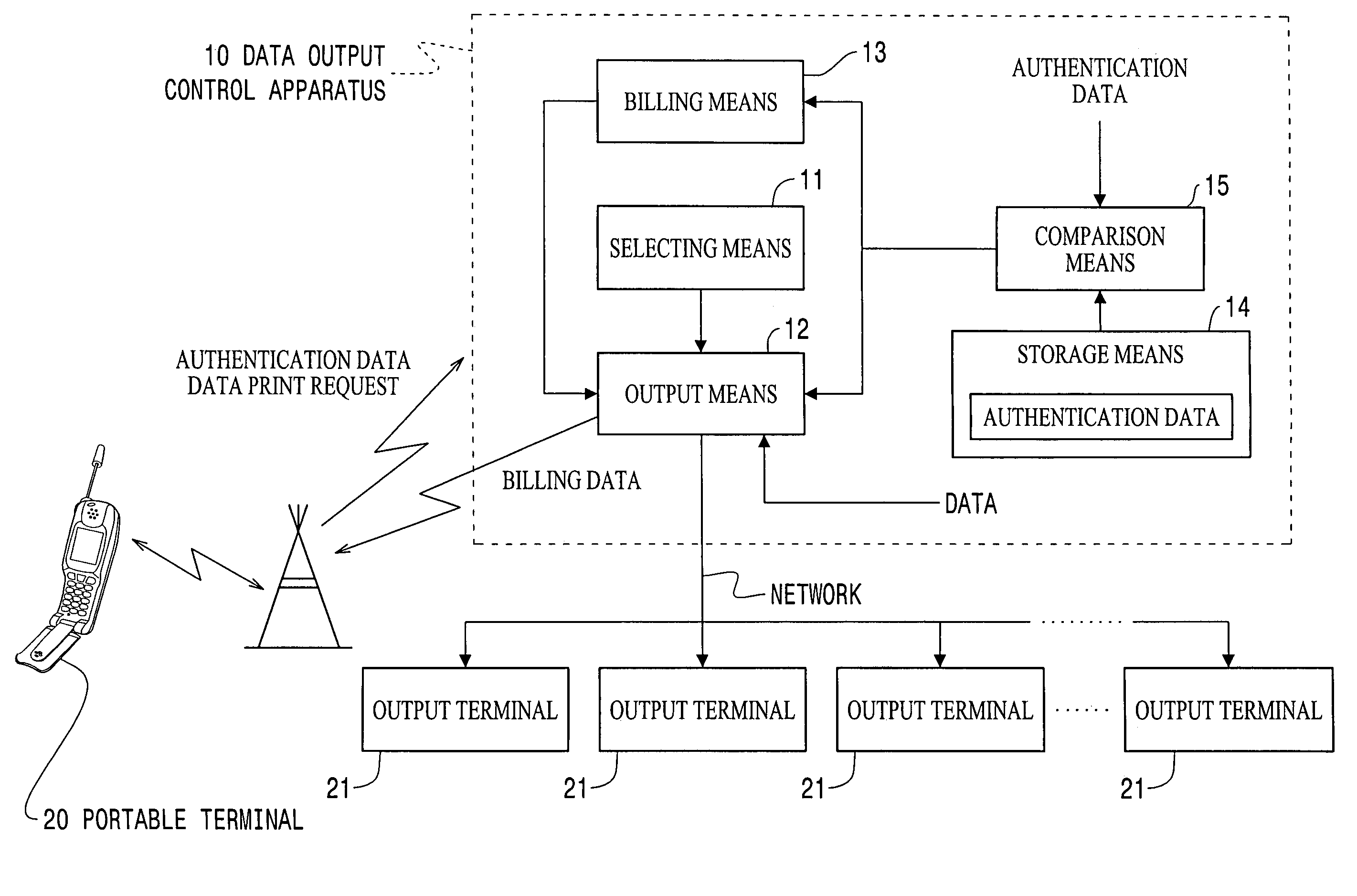
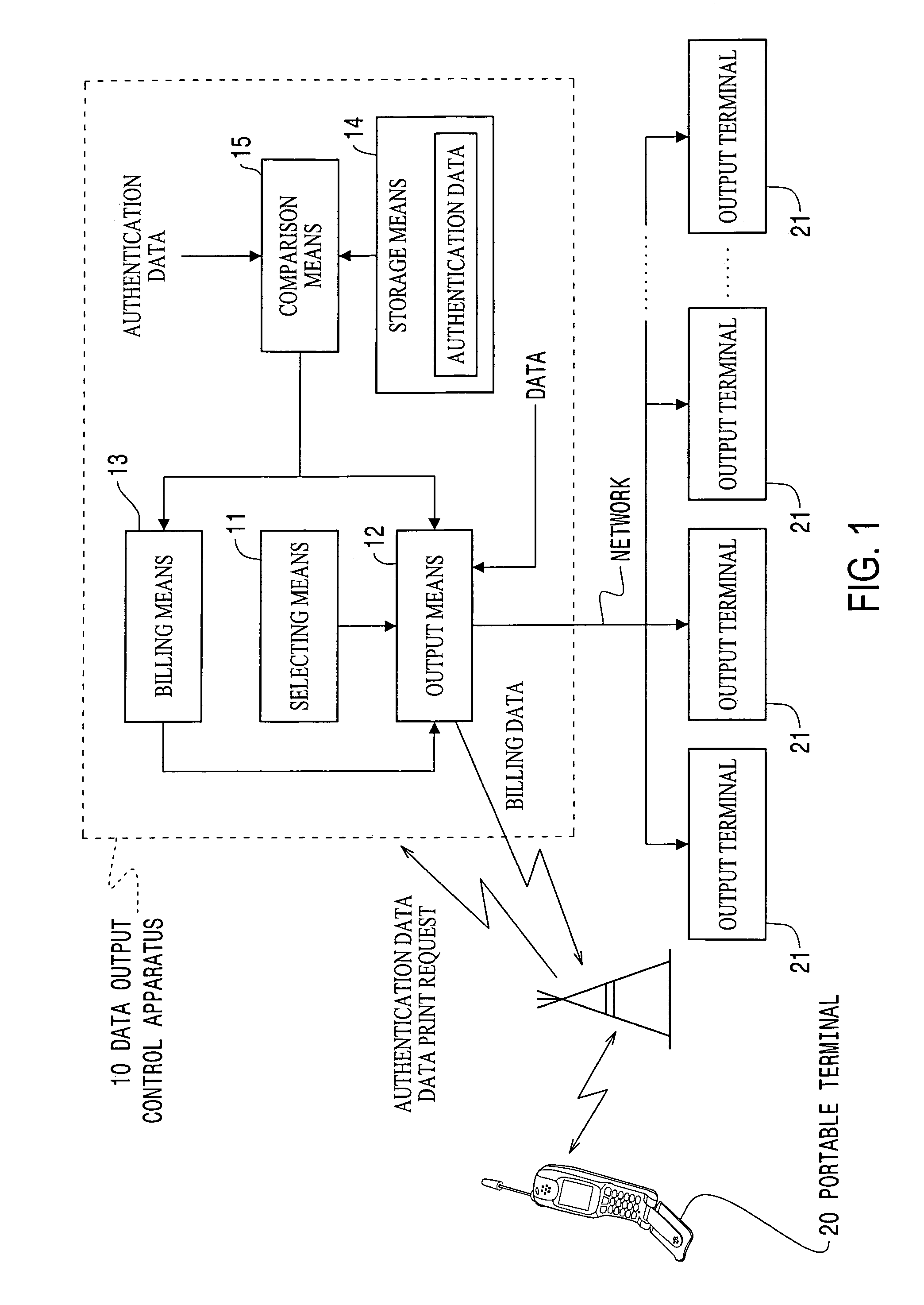
[0058]In this embodiment, as shown in FIG. 2, the data output control apparatus according to the present invention is applied to a case where, by a portable terminal 100 carried by a user, such as a cellular phone, and a data output control terminal 300 communicatively connected via the Internet 400 to printing apparatuses PR1 to PRn respectively provided at a plurality of shops S1 to Sn existing at various locations, a service provider, in response to a data print request from the user, provides a service wherein data associated with the data print request received from one of WWW (World Wide Web) servers DS1 to DSm is obtained and output to one of the printing apparatuses PR1 to PRn. For ease in understanding the present invention, only a single portable termin...


PUM


Abstract

The object is to provide a data output control apparatus which allows detailed information on a network to be readily obtained, which is advantageous with respect to cost, and which is suitable for specifically notifying the user of the service charge.A data output control terminal 300 is communicatively connected via the Internet 400 to a portable terminal 100 carried by a user, printing apparatuses PR1 to PRn provided at various locations, and WWW servers DS1 to DSm. The data output control terminal 300 obtains from a WWW server DS data associated with a data print request from the portable terminal 100, selects one of the plurality of printing apparatuses PR, and outputs the obtained data to the selected printing apparatus. Billing is executed in accordance with the result of use by the portable terminal 100 of the print service provided by the data output control terminal 300. The billing is executed by summing the service charge and the call charge of the portable terminal 100.

Description

TECHNICAL FIELD[0001]The present invention relates to an apparatus, and a method therefor, which is communicatively connected via a network to a portable terminal carried by a user and to a plurality of printing apparatuses provided at various locations, and which outputs, in response to a data print request from the portable terminal, data associated with the data print request to one of the printing apparatuses. More specifically, it relates to a data output control apparatus which allows detailed information on a network to be readily obtained, which is advantageous with respect to cost, and which is suitable for specifically notifying the user of the service charge.BACKGROUND ART[0002]In recent years, information on the Internet is readily available anywhere using, for example, i-mode™ provided by NTT Mobile Communications Network, Inc. (NTT DoCoMo).[0003]However, although such a portable terminal allows information on the Internet to be readily obtained anywhere, because the co...

Claims


Application Information

Patent Timeline
Patent Type & Authority Patents(United States)
IPC IPC(8): G06Q40/00G06F3/12G06F13/00G06Q20/10H04M15/00H04W4/24H04W28/00
CPCG06F3/122G06F3/1238G06F3/126G06F3/1273G06F3/1288G06F3/1292G06Q20/10G06Q20/102G06Q20/105G06Q40/00H04M15/00H04M15/44H04M15/68H04M15/81H04M15/83H04M15/84H04W4/24G06F3/1265H04M2215/0104H04M2215/0112H04M2215/0176H04M2215/0196H04M2215/2026H04M2215/22H04M2215/32H04M2215/81H04M2215/8129H04M2215/82
Inventor AOKI, MIKIOTANIGUCHI, SHINYA
Owner SEIKO EPSON CORP
Why Eureka
Try Eureka