Display controller, display unit and electronic apparatus

a display controller and electronic equipment technology, applied in the field of display controllers, display units and electronic equipment, can solve the problems of increasing the current consumption proportional to frequencies, short battery run time of mobile electronic equipment such as a mobile telephone, increasing the number of gradation bits,

Inactive Publication Date: 2002-12-12
SEIKO EPSON CORP
View PDF4 Cites 28 Cited by
  • Summary
  • Abstract
  • Description
  • Claims
  • Application Information

AI Technical Summary

Benefits of technology

[0011] In accordance with the present invention, in the display controller having the storage device that stores display data for one frame, and the display section is display-driven based on the display data stored in the storage device, display data to be written in the storage device is received during a dummy blanking period provided prior to a start of scanning at the display section and the same is successively written in the storage device. By doing so, display data for a picture to be displayed in each frame can be received quickly, and written in the storage device. Therefore, even where the amount of display data increases with increases in the screen size of display sections and increases in the number of gradation bits, transfer time required to transfer thereof can be secured.
[0036] The present invention can provide an electronic apparatus that can display a variety of pictures including moving pictures at a low power consumption even where the amount of display data for one frame increases due to an increase in the screen size or an increase in the number of gradation bits.

Problems solved by technology

However, in the CMOS circuit, its current consumption increases in proportion to frequencies.
Therefore, where a transfer rate that is required to display moving pictures without causing a feeling of physical disorder is realized, the battery run time of a mobile electronic apparatus, such as a mobile telephone, becomes short.
Also, interfaces formed from CMOS circuits would make it difficult to realize transfer rates that can accommodate increases in the screen size of liquid crystal panels and increases in the number of gradation bits in the future.

Method used


Image

  • Display controller, display unit and electronic apparatus
  • Display controller, display unit and electronic apparatus
  • Display controller, display unit and electronic apparatus

Examples


first embodiment

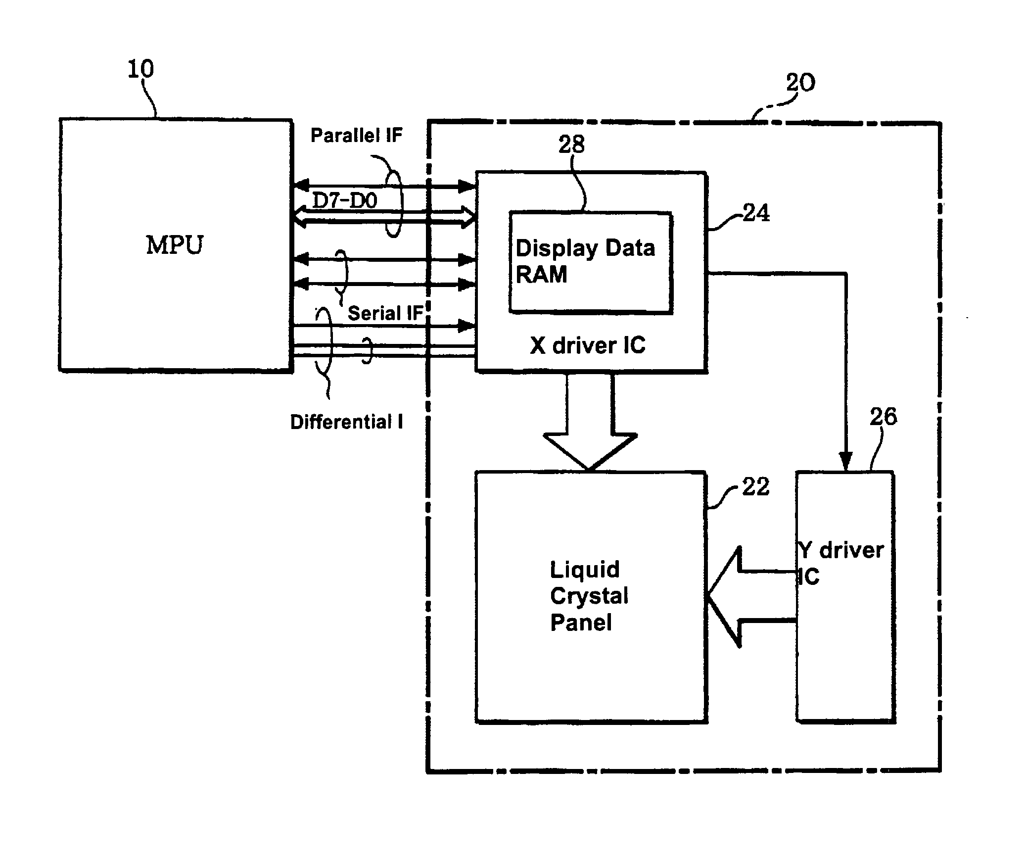
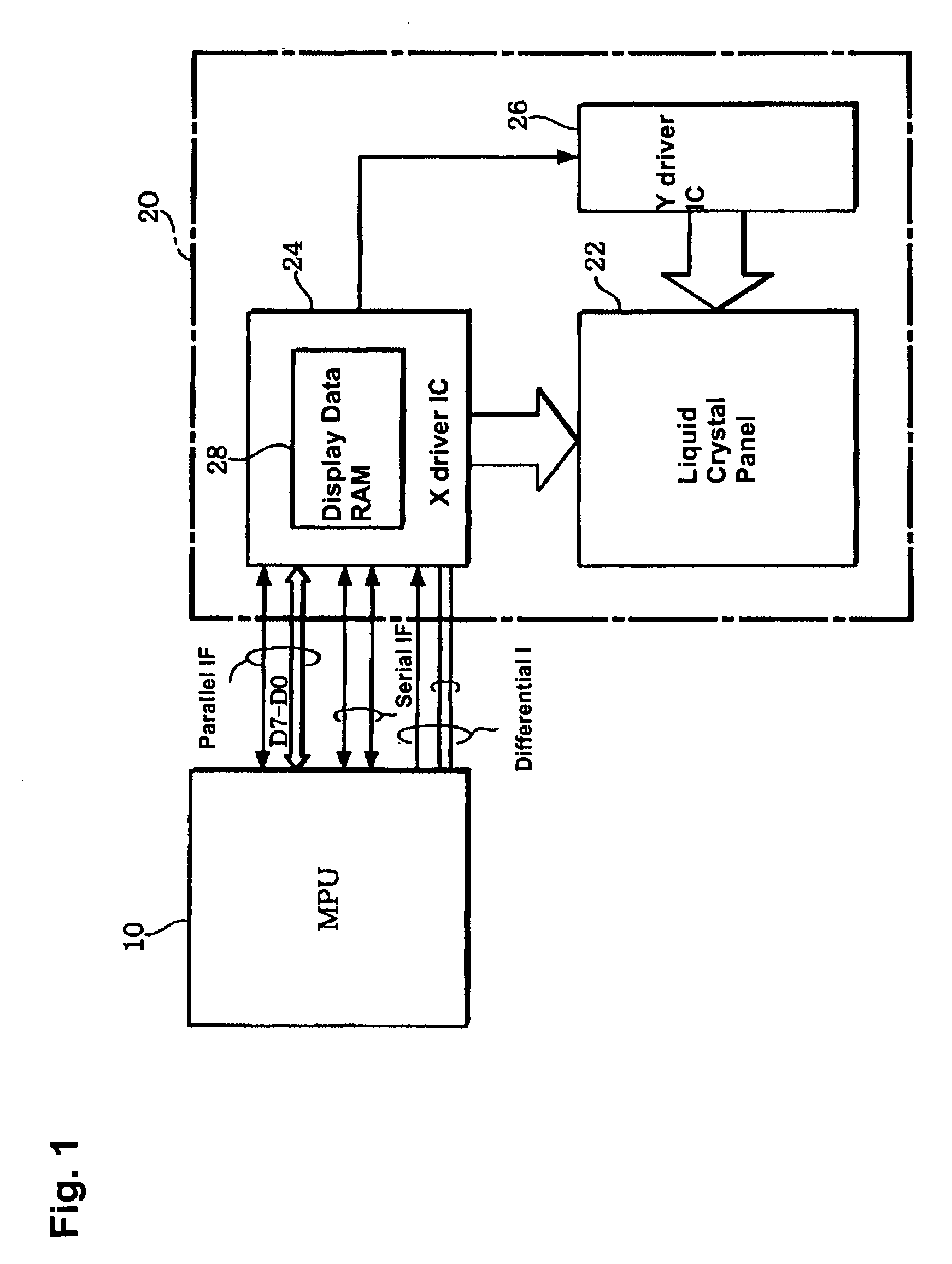
[0056] FIG. 1 shows one example of a summary structure of an electronic apparatus in which a display controller in accordance with the present invention.

[0057] The electronic apparatus includes an MPU (Micro Processor Unit) (a display data supply circuit in a broader sense) 10, and a display unit 20. The MPU 10 supplies to the display unit 20 one of moving picture data and still picture data or both moving and still picture data. The display unit 20 display-drives a display section based on display data supplied from the MPU 10. Here, the display data is, for example, moving picture data, still picture data, and data that are required to display-drive the display section with display control signals for the picture data.

[0058] The display unit 20 includes a matrix panel with electrooptic elements, such as a color liquid crystal panel (a display section in a broader sense) 22, an X driver IC with a built in RAM (a display controller in a broader sense) 24 that drives the liquid cryst...

first structure example

[0112] FIG. 6(A) is a schematic that shows a first example of a structure of a differential IF, and FIG. 6(B) is a schematic that shows one example of an operation waveform of the first structure example.

[0113] The first structure example is provided with a differential driver 100 on the transfer side and a differential receiver 102 on the reception side, which are connected to one another through signal lines D1 and D2 of a differential pair. The differential driver 100 is structured to be included in the differential IF circuit 42 of the MPU in FIG. 2. Also, the differential receiver 102 is structured to be included in the differential IF circuit 60 in FIG. 3.

[0114] The differential driver 100 on the transfer side includes a p-type (a first conductive type) transistor 104 (a differential driver control device in a broader sense) with its source terminal being connected to a power supply VDD (a first power source), and its gate terminal receiving a power control signal PS. A drain ...

second structure example

[0128] FIG. 8(A) is a schematic that shows a second example of a structure of a differential IF, and FIG. 8(B) is a schematic that shows one example of an operation waveform of the second structure example.

[0129] The second structure example is provided with a differential driver 130 on the transfer side and a differential receiver 132 on the reception side, which are connected to one another through signal lines D1 and D2 of a differential pair. The differential driver 130 is structured to be included in the differential IF circuit 42 of the MPU in FIG. 2. Also, the differential receiver 132 is structured to be included in the differential IF circuit 60 in FIG. 3.

[0130] The differential driver 130 on the transfer side includes a p-type transistor 134 (a differential driver control device in a broader sense) with its source terminal being connected to a power supply VDD, and its gate terminal receiving a power control signal PS. A drain terminal of the p-type transistor 134 is conne...


PUM

PropertyMeasurementUnit
currentaaaaaaaaaa
bit widthaaaaaaaaaa
widthaaaaaaaaaa

Abstract

The invention provides display controllers, display units and electronic apparatuses using the same, which can achieve transfer rates that can accommodate increases in the amount of display data that may result from increases in the screen size of liquid crystal panels in the future with low power consumption. The display unit includes a liquid crystal panel (display section), a display data RAM that stores display data for at least one frame, an X driver IC (display controller) that display-drives the liquid crystal panel at a given frame cycle, and a Y driver IC that scan-drives the liquid crystal panel. Display data is supplied from the MPU to the X driver IC through a differential IF. The MPU supplies display data at a high-speed transfer rate with the differential IF, using a dummy blanking period, and stops the operation of the differential IF until the next display data transfer timing.

Description

[0001] 1. Field of Invention[0002] The present invention relates to display controllers, display units and electronic apparatuses using the same.[0003] 2. Description of Related Art[0004] Due to recent developments in communication technology and mounting technology, characters, such as numbers and letters, as well as a variety of data that are highly informative to users, such as still pictures and moving pictures, can be displayed on display sections of mobile type electronic apparatuses. A variety of data formats have been proposed for data that are displayed on such electronic apparatuses. For example, in the case of mobile telephones, a technology that receives or transfers display data that is compressed and coded by the MPEG (Moving Picture Experts Group) standard has been proposed.[0005] In this case, a mobile telephone may be equipped with a liquid crystal panel as its display section, for example. The liquid crystal panel is display-driven with a display controller based o...

Claims


Application Information

Patent Timeline
Patent Type & Authority Applications(United States)
IPC IPC(8): G02F1/133G06F3/147G09G3/20G09G3/36H04M1/73
CPCG06F3/147H04W52/027G09G2330/021Y02D30/70
Inventor KOIZUMI, NORIO
Owner SEIKO EPSON CORP
Why Eureka
Try Eureka