Phase-differential quantum key allocation and allocating system

A key distribution system and key distribution technology, applied in the field of one-way, stable, fast phase difference quantum key distribution method and its system, can solve the problem of limited transmission distance, poor stability, easy to receive interference from external environment, etc. problem, to achieve high communication security, avoid theft, and fast quantum key distribution

Inactive Publication Date: 2007-01-17
SOUTH CHINA NORMAL UNIVERSITY
View PDF0 Cites 28 Cited by
  • Summary
  • Abstract
  • Description
  • Claims
  • Application Information

AI Technical Summary

Problems solved by technology

[0004] The phase difference system uses two pulses in time for phase encoding at the transmitting end, and uses the response results of two detectors for decoding at the receiving end, thus saving the phase modulator at the receiving end, reducing the insertion loss of the line and greatly The transmission efficiency is improved; however, this system is extremely susceptible to interference from the external environment when phase modulation is performed at the transmitter end and interference detection at the receiver end, and the stability is poor
Although the currently developed optical waveguide integration technology can avoid these factors to a certain extent, its

Method used


Image

  • Phase-differential quantum key allocation and allocating system
  • Phase-differential quantum key allocation and allocating system
  • Phase-differential quantum key allocation and allocating system

Examples


Embodiment 1

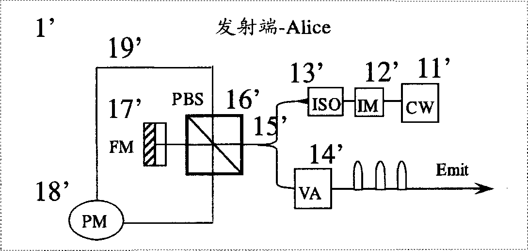
[0050] Such as figure 1 The shown signal modulation transmitter 1'uses an intensity modulator 12' to modulate the laser light emitted by the continuous laser light source 11' into coherent pulsed light with equal time intervals of Δt, and then enters the four-port polarization beam splitter 16' to be divided into horizontal and vertical Two beams of polarized light. One beam of light directly enters the phase modulator 18', and the other beam of light passes through the Faraday rotator mirror 17' to rotate the polarization plane by 90 degrees, and then enters the phase modulator 18' from the other end. The distance of the optical fiber 19' is designed so that the two The beam of light reaches the phase modulator 18' at the same time. Since the two beams experience the same optical path, they are recombined at the 16' port of the polarization beam splitter. Therefore, according to the phase modulation information {0,π}, a random quantum code is output, and then it is attenuated to...

Embodiment 2

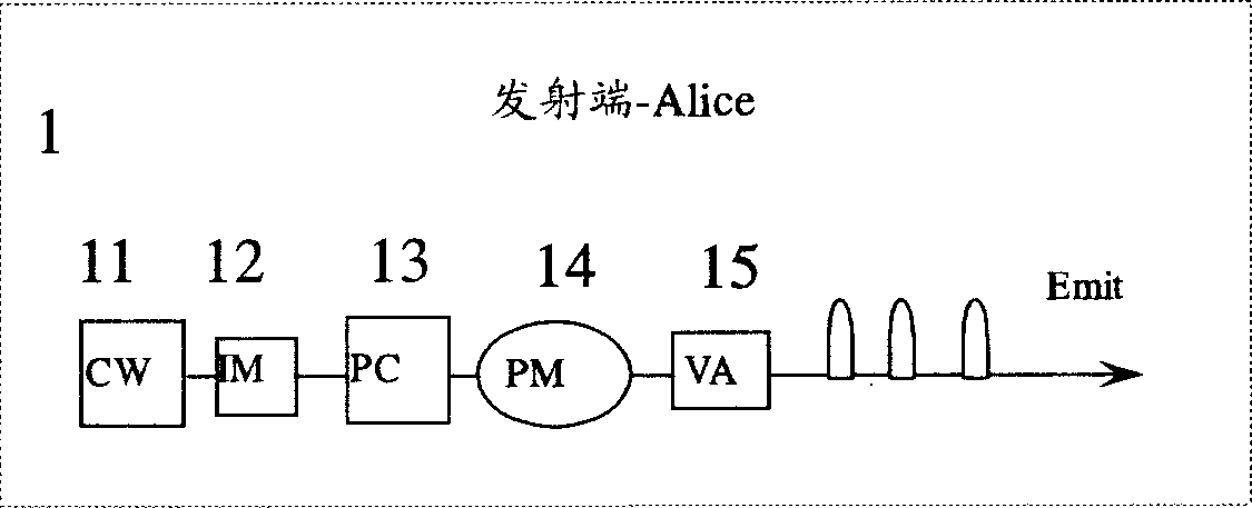
[0055] Such as figure 2 The signal modulation transmitter 1 shown directly uses the intensity modulator 12 to modulate the laser light emitted by the continuous laser light source 11 into coherent pulsed light with equal time intervals of Δt, and enters the phase modulator 14 after being controlled by the polarizer 13. After loading the phase modulation information {0, π}, it is attenuated to a single quantum state μ=0.1 through the optical attenuator 15. In this way, the structure is simple, the devices used are less, the price is low, and the stability is good. The receiving end of the system is exactly the same as in the first embodiment.

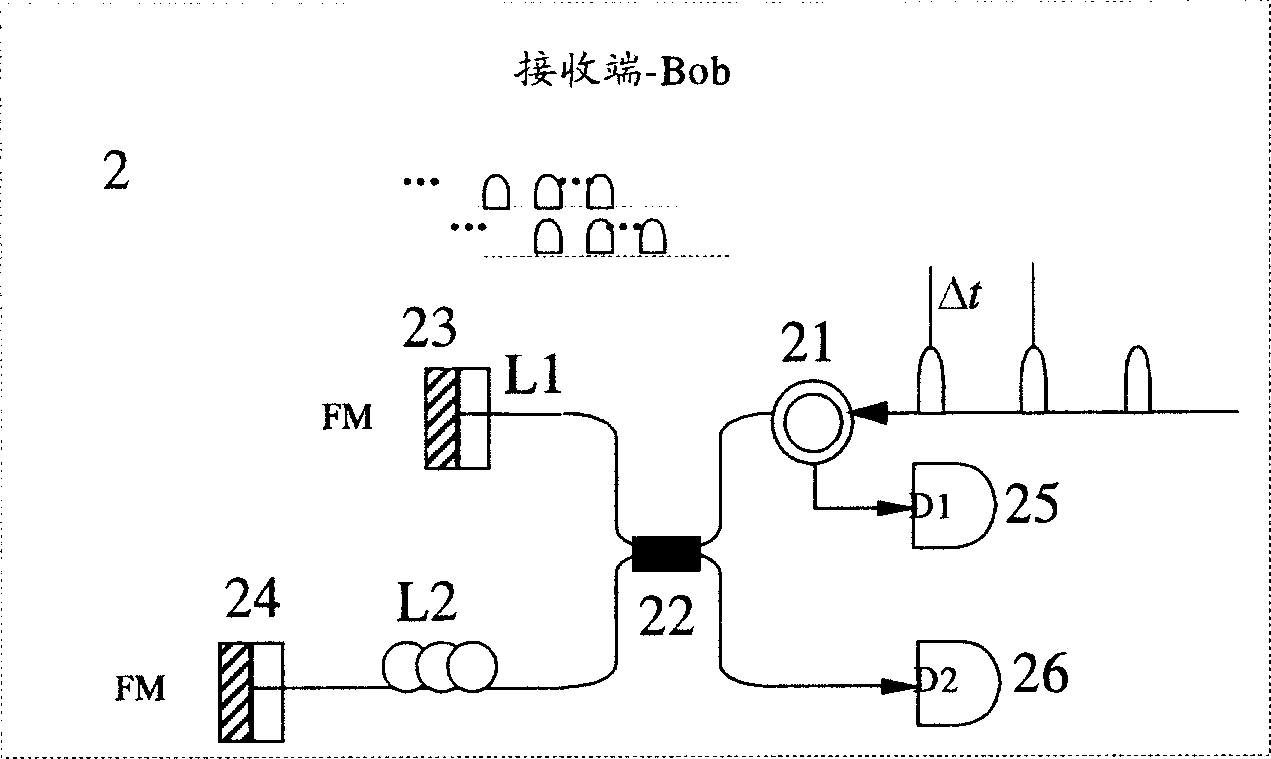
[0056] Light path like Figure 5 As shown, at the transmitting end, Alice modulates each pulse with 0 or π random phase. It is specified that when the phase is 0, the code is "0", and when the phase is π, it is the code "1". The signal is transmitted to the receiving end through the optical fiber 10. At the receiving end, Bob uses the detect...


PUM


Abstract

The invention manages to provide a stable and fast differential quantum key distribution method and system thereof. At transmitting end, with a continuous laser source, the quantum codes are prepared using two approaches: 1) using the beam-splitting, polarization-independent and phase-stabilizing approach to prepare the stable quantum code; 2) using polarization approach to directly prepare stable quantum code. At receiving end,differential phase-Faraday-Micheal test approach is used to directly receive the quantum information.

Description

Technical field [0001] The invention relates to the field of special equipment for quantum secure communication in the field of communication, in particular to a unidirectional, stable and fast phase differential quantum key distribution method and system. technical background [0002] Quantum secure communication is currently the only method of communication that has been proven to be absolutely secure. Using single photons as information carriers to transmit quantum information bits, its security is guaranteed by the uncertainty principle in quantum mechanics and the unclonability theorem of unknown quantum states. This kind of absolutely secure quantum cryptography will first be applied to military, national security and other fields, and it will become a new battlefield for scientists from all over the world to compete. [0003] According to the encoding and decoding methods, the existing quantum secure communication system is divided into three encoding methods: polarization...

Claims


Application Information

Patent Timeline
IPC IPC(8): H04L9/08
Inventor 赵峰路铁群王发强廖常俊刘颂豪
Owner SOUTH CHINA NORMAL UNIVERSITY
Why Eureka
Try Eureka