Flow measurement diagnostics

a technology of flow measurement and diagnostics, applied in the direction of volume metering, instruments, nuclear elements, etc., can solve the problems of no longer being able to track, affecting the operation of the transmitter, and pressure drop and increased turbulen

Inactive Publication Date: 2006-12-07
ROSEMOUNT INC
View PDF99 Cites 53 Cited by
  • Summary
  • Abstract
  • Description
  • Claims
  • Application Information

AI Technical Summary

Problems solved by technology

Flow around the discontinuity causes both a pressure drop and increased turbulence.
Impulse lines can become plugged over time which isolates the pressure transmitter from the process such that t...

Method used


Image

  • Flow measurement diagnostics
  • Flow measurement diagnostics
  • Flow measurement diagnostics

Examples


Embodiment Construction

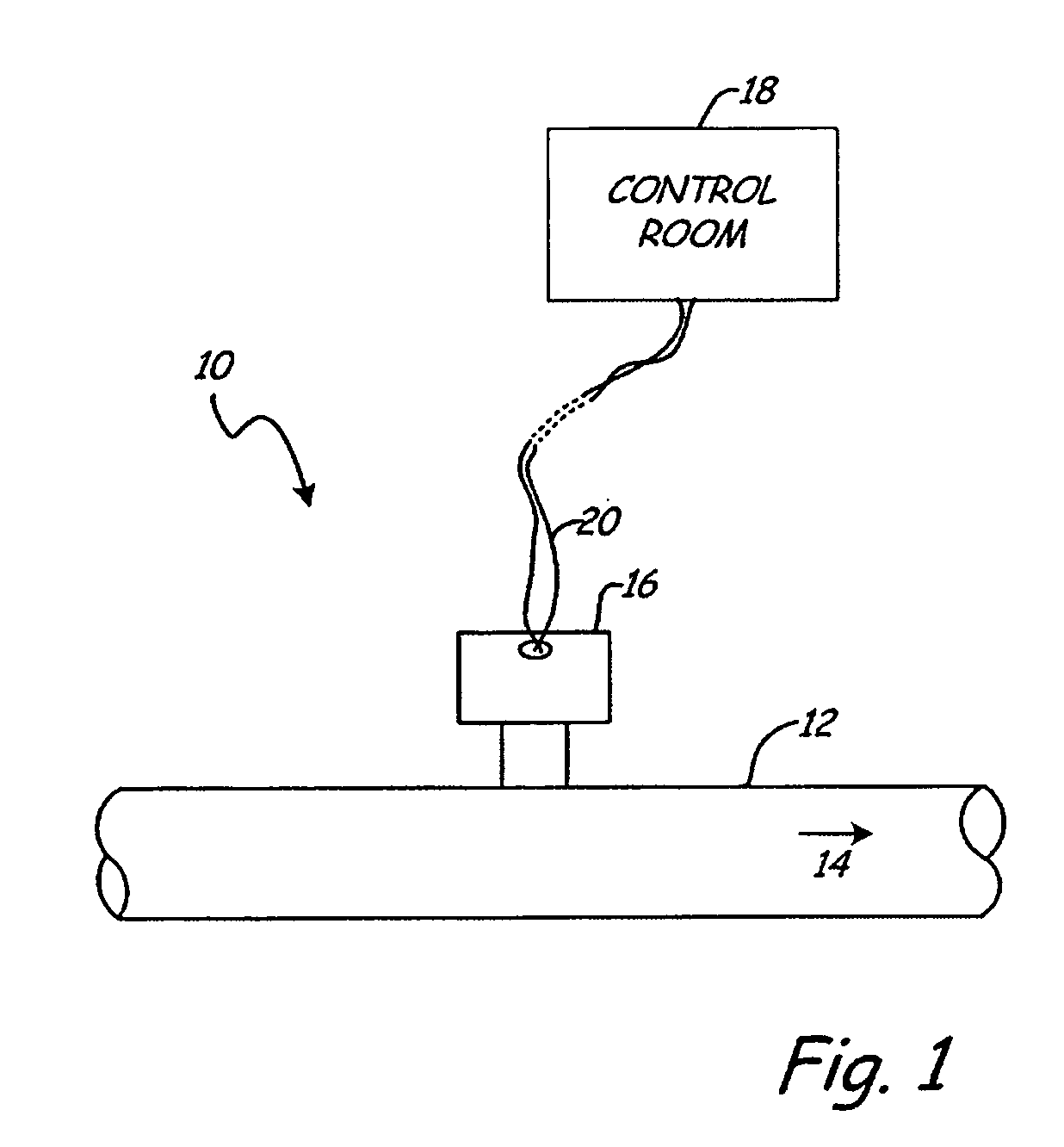
[0010]FIG. 1 is a simplified diagram of a process control or monitoring system 10 in which process piping 12 carries a flow 14 of process fluid. A flow transmitter 16 is configured to sense the flow 14 and provide an output related to the flow 14. In the example shown in FIG. 1, the output is provided to control room 18 over a two wire process control loop 20. Loop 20 can operate in accordance with any protocol. Example standard protocols includes 4-20 mA signals, the HART® communication protocol or Fieldbus protocols. However, the present invention is not limited to such communication techniques, including wireless techniques, and can even operate in a stand alone device.

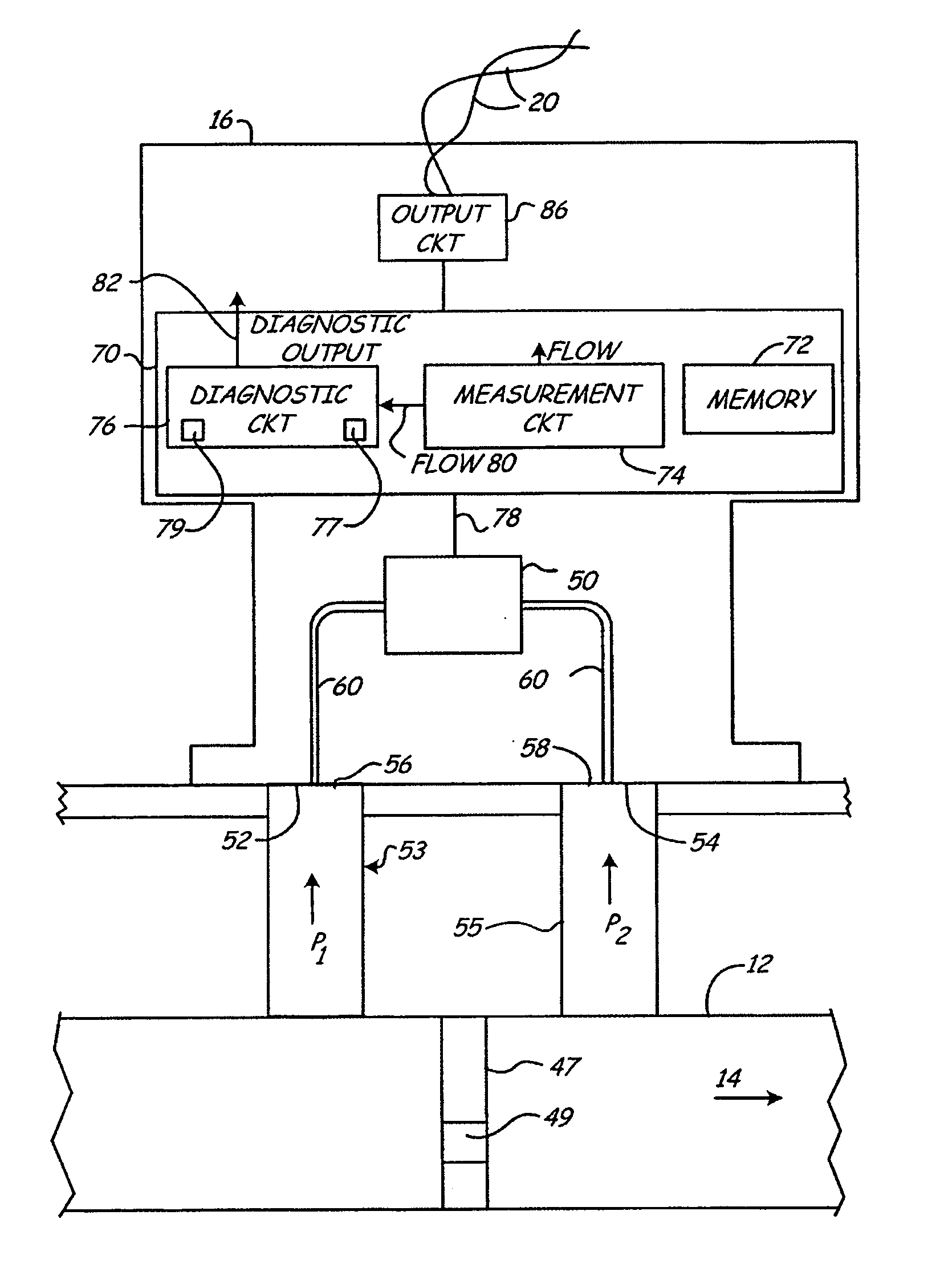
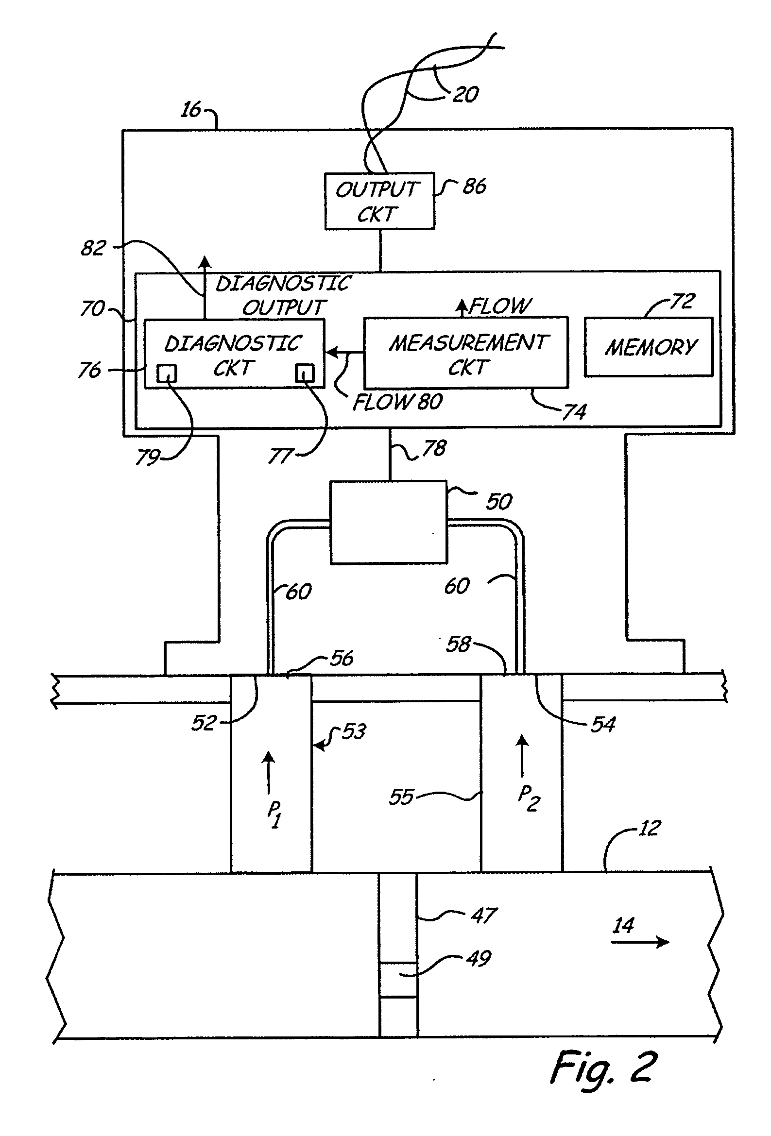
[0011] Process variable transmitter 16 senses flow using any appropriate technique. Example techniques include measuring a differential pressure across a restriction in the pipe 12, magnetic based technologies, pitot tubes, vibrating sensors, etc.

[0012] In accordance with the invention, transmitter 16 provides a ...


PUM


Abstract

A flow meter for measuring flow of a process fluid includes a sensor configured to provide a sensor output signal. The sensor output signal is related to flow of the process fluid. Circuitry in the flow meter is configured to determine a statistical parameter related to sensor output signal. Diagnostic circuitry provides a diagnostic output based upon the determined statistical parameter and the sensor output signal.

Description

[0001] The present invention is a Continuation-In-Part of and claims priority to U.S. application Ser. No. 10 / 801,073, filed Mar. 15, 2004, which is a Continuation-In-Part of U.S. application Ser. No. 09 / 852,102, now U.S. Pat. No. 6,907,383, which is a Continuation-In-Part of U.S. application Ser. No. 09 / 257,896, filed Feb. 25, 1999, abandoned which is a Continuation-In-Part of U.S. application Ser. No. 08 / 623,569, now U.S. Pat. No. 6,017,143, application Ser. No. 09 / 852,102 is also a Continuation-In-Part of U.S. application Ser. No. 09 / 383,828, now U.S. Pat. No. 6,654,697, which is a Continuation-In-Part of U.S. application Ser. No. 09 / 257,896, filed Feb. 25, 1999 which is a Continuation-In-Part of U.S. application Ser. No. 08 / 623,569, filed Mar. 28, 1996, now U.S. Pat. No. 6,017,143.BACKGROUND OF THE INVENTION [0002] The present invention relates to fluid process control and monitoring systems. In particular, the present invention relates to diagnostics for such systems. [0003] Fl...

Claims


Application Information

Patent Timeline
IPC IPC(8): G21C17/00
CPCG01F25/0007G01F15/00G01F25/10
Inventor WEHRS, DAVID L.
Owner ROSEMOUNT INC
Why Eureka
Try Eureka