Electrical power contacts and connectors comprising same
What is AI technical title?
AI technical title is built by Patsnap AI team. It summarizes the technical point description of the patent document.
a technology of electrical contacts and connectors, applied in the direction of coupling contact members, coupling device connections, electrical apparatus, etc., can solve the problems of increasing power transmission, dimensional constraints, undesirable heat buildup, affecting the mechanical and electrical performance of the connector, etc., to achieve the effect of reducing stress
Active Publication Date: 2006-12-14
FCI AMERICAS TECH LLC
View PDF29 Cites 85 Cited by
Summary
Abstract
Description
Claims
Application Information
AI Technical Summary
This helps you quickly interpret patents by identifying the three key elements:
Problems solved by technology
Method used
Benefits of technology
Benefits of technology
[0010] In accordance with yet another preferred embodiment, there has now been provided matable power contacts including first and second power contacts. The first power contact includes a body member, a deflecting beam extending from the body member, and a non-deflecting beam extending from the body member. The second power contact includes a second body member, a second deflecting beam extending
Problems solved by technology
For example, increased power transmission often competes with dimensional constraints and undesirable heat buildup.
Further, typical power connector and contact beam designs can create high mating forces
Method used
Image
Click on the blue label to locate the original text in one second.
Reading with bidirectional positioning of images and text.
Examples
Embodiment Construction
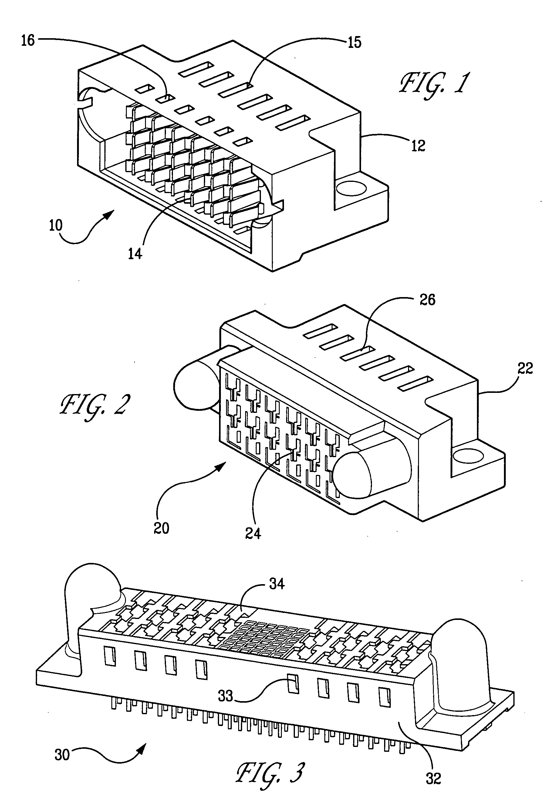
[0004] The present invention provides power contacts for use in an electrical connector. In accordance with one preferred embodiment of the present invention, there has now been provided a power contact including a first plate-like body member, and a second plate-like body member stacked against the first plate-like body member so that the first and second plate-like body members are touching one another along at least a portion of opposing body member surfaces.
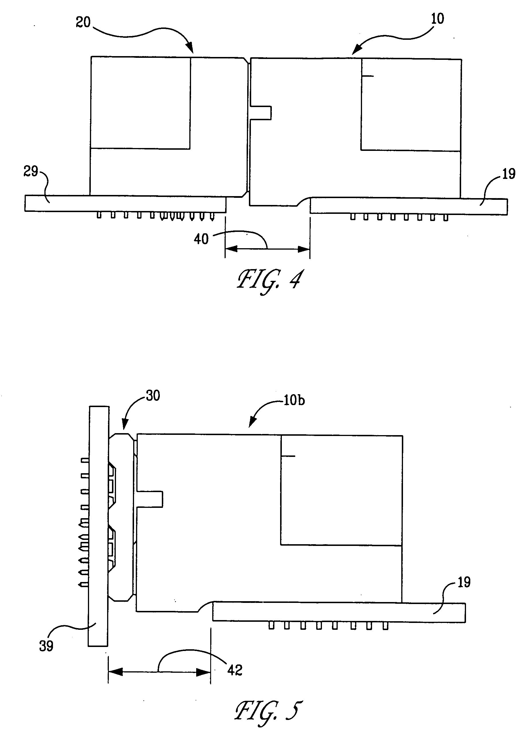
[0005] In accordance with another preferred embodiment of the present invention, there has now been provided a power contact including juxtaposed first and second plate-like body members that define a combined plate width. The first body member includes a first terminal and the second body member includes a second terminal. A distance between respective distal ends of the first terminal and the second terminal is greater than the combined plate width.
[0006] In accordance with yet another preferred embodiment, there has now ...
PUM
Abstract
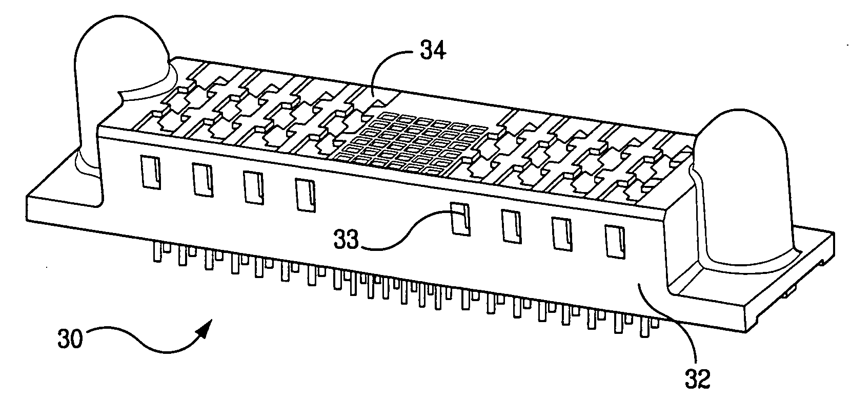
Preferred embodiments of power contacts include two or more opposing contact beams of a first type that are spaced apart along at least a portion of the length thereof when the power contact is in an unmated state; and two or more opposing contact beams of a second type. The contact beams of the second type are spaced apart so that the contact beams of the second type pinch the contact beams of the first type when the power contact is mated with a mating contact, thereby causing the contact beams of the first type of deflect inwardly toward each other.
Description
CROSS REFERENCE TO RELATED APPLICATIONS [0001] This application is a continuation in part of application Ser. No. 11 / 019,777, filed Dec. 21, 2004, which claims the benefit of U.S. Provisional Application Nos. 60 / 533,822, filed on Dec. 31, 2003, 60 / 533,749, filed Dec. 31, 2003, 60 / 533,750, filed Dec. 31, 2003, 60 / 534,809, filed Jan. 7, 2004, 60 / 545,065, filed Feb. 17, 2004. This application is related to U.S. application Ser. No. 11 / 019,777, filed Dec. 21, 2004; U.S. application Ser. No. 11 / 408,437, filed Apr. 21, 2006; and U.S. application titled “Connectors and Contacts for Transmitting Electrical Power,” filed May 26, 2006 with attorney docket no. FCI-3004 / C3980. The contents of each of these applications is incorporated by reference herein in its entirety.FIELD OF THE INVENTION [0002] The present invention relates to electrical contacts and connectors designed and configured for transmitting power. At least some of the preferred connector embodiments include both power contacts a...
Claims
Application Information
Patent Timeline
Application Date:The date an application was filed.
Publication Date:The date a patent or application was officially published.
First Publication Date:The earliest publication date of a patent with the same application number.
Issue Date:Publication date of the patent grant document.
PCT Entry Date:The Entry date of PCT National Phase.
Estimated Expiry Date:The statutory expiry date of a patent right according to the Patent Law, and it is the longest term of protection that the patent right can achieve without the termination of the patent right due to other reasons(Term extension factor has been taken into account ).
Invalid Date:Actual expiry date is based on effective date or publication date of legal transaction data of invalid patent.
IPC IPC(8): H01R13/28H01R13/04H01R13/115
CPCH01R13/113H01R12/727H01R12/7088H01R13/28
InventorNGO, HUNG VIETDAILY, CHRISTOPHER G.SWAIN, WILFRED J.STONER, STUART C.KOLIVOSKI, CHRISTOPHER J.JOHNESCU, DOUGLAS M.

