
Umbrella device

a technology of umbrellas and umbrella covers, which is applied in the field of umbrella covers, can solve the problems of inconvenience of carrying an umbrella, inconvenient carrying an umbrella, and unpleasant carrying of a wet umbrella after us

Inactive Publication Date: 2006-12-21
HO WING HANG
View PDF5 Cites 10 Cited by
  • Summary
  • Abstract
  • Description
  • Claims
  • Application Information

AI Technical Summary

Benefits of technology

[0016] The distal end of the arm assembly may be operatively connected to the canopy mechanism such that the operation of the umbrella device simultaneously expands the canopy in the extended open configuration and collapses the canopy in the retracted closed configuration. This arrangement provides the umbrella device an automation feature, allowing both hands of the user free for other purposes.

Problems solved by technology

This may not be convenient for the user in circumstances where pointing the umbrella away from the user is difficult or where it is desirable to hold the device in a fixed position during deployment and use of the umbrella.
It is also often inconvenient to carry an umbrella particularly if the user requires the use of both hands for other purposes.
Further, carrying a wet umbrella after use is somewhat unpleasant.
The drawback of these devices is that although the user wears the holder attached to the torso, it is still necessary to take a separate umbrella by hand and mount and detach it, before and after every use.
The belt is made of a rigid metal which is uncomfortable to wear and makes sitting difficult.
Although this device enables the user to fold and unfold a mounted umbrella without requiring the umbrella to be removed from the device, the umbrella shaft must be arranged behind the user to avoid interfering with the face of the user and is therefore not easily accessible.

Method used


Image

  • Umbrella device
  • Umbrella device
  • Umbrella device

Examples


Embodiment Construction

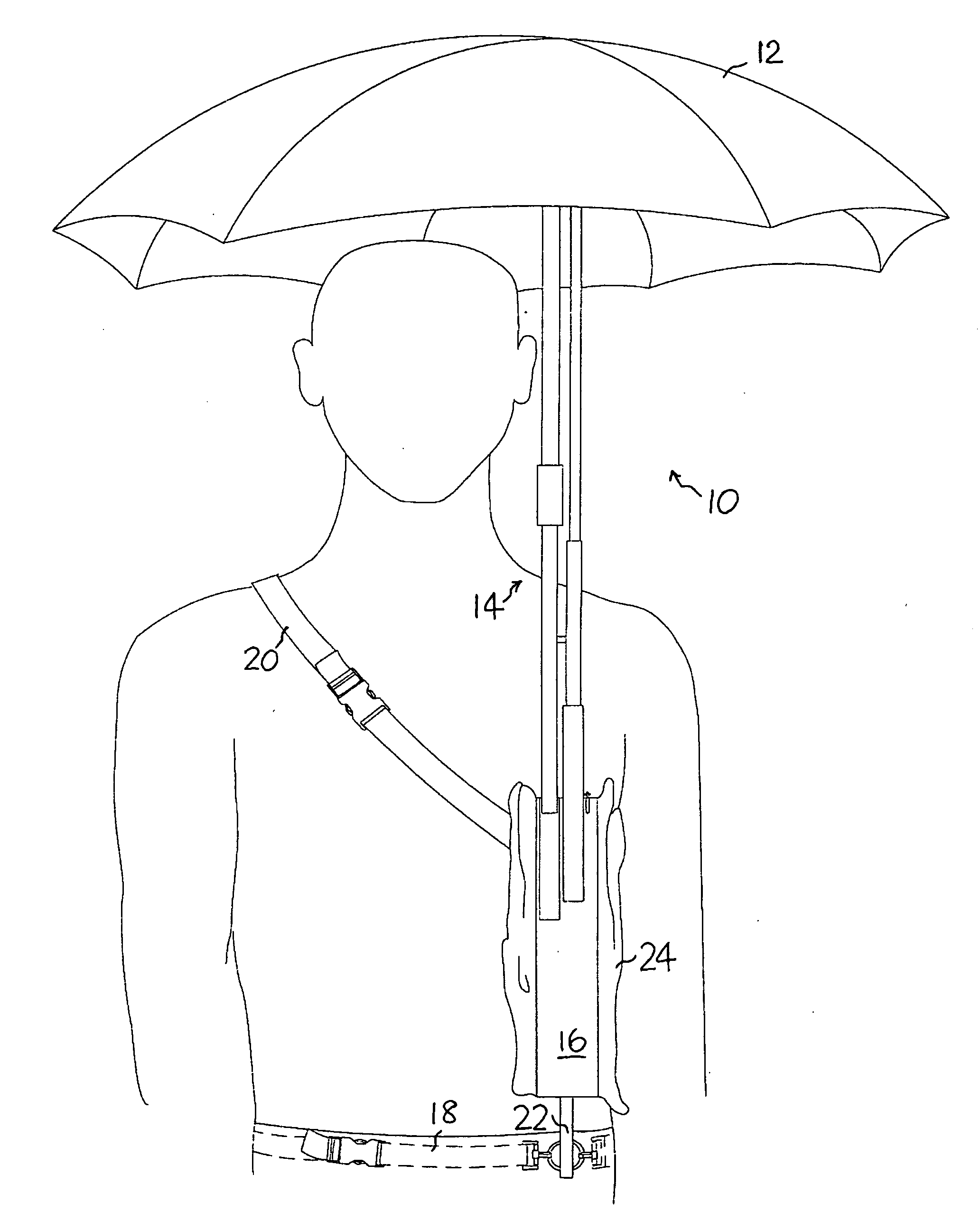
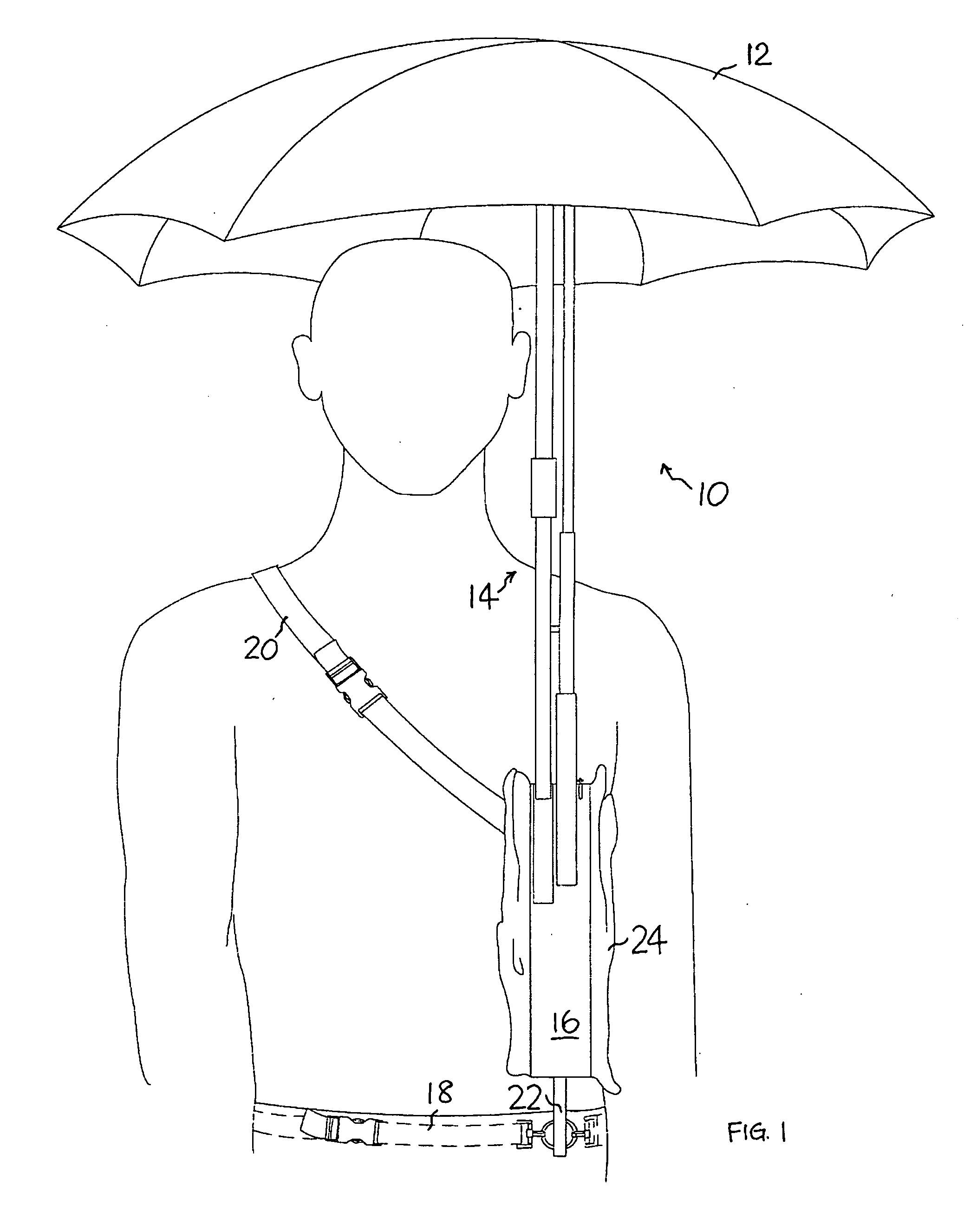
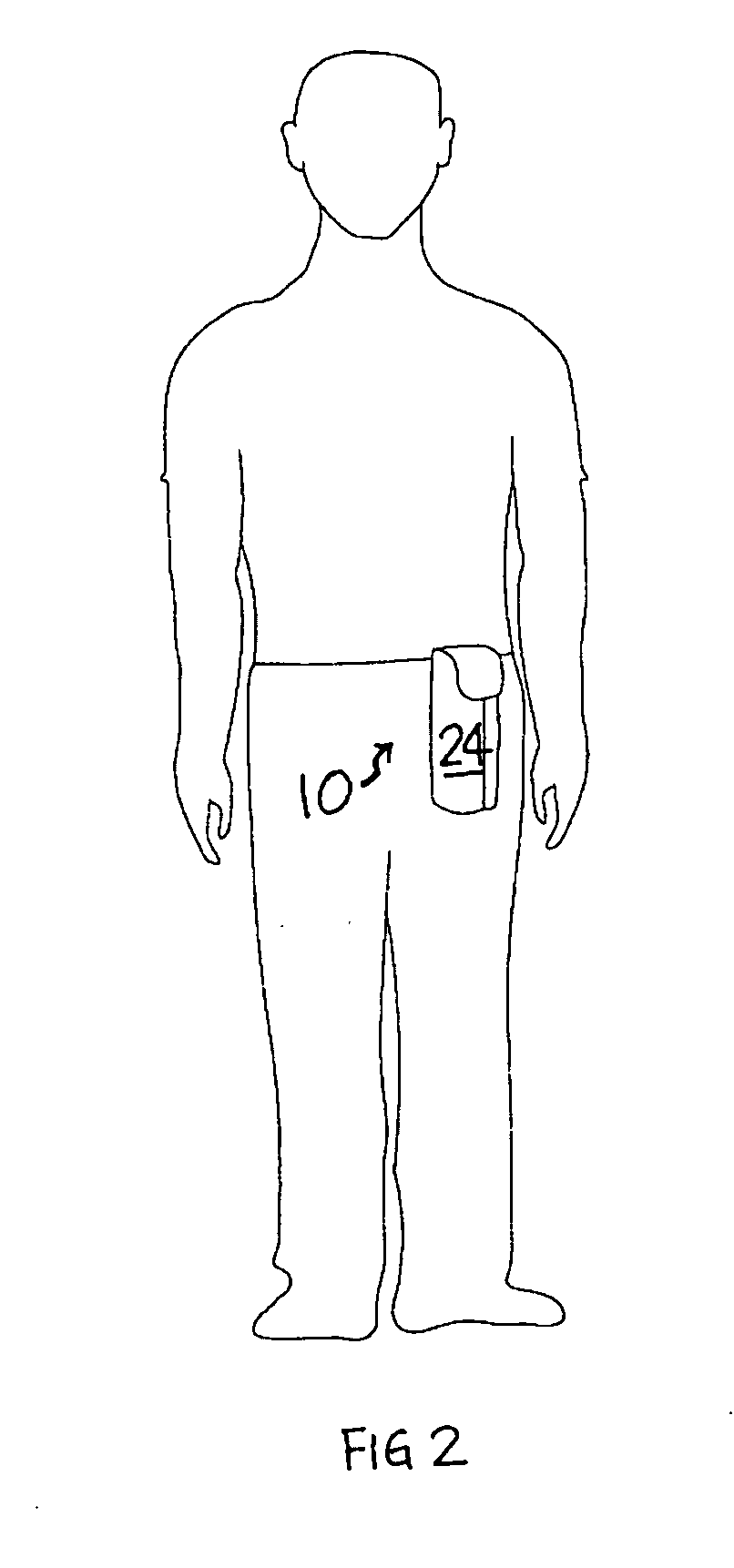
[0075] Referring to FIGS. 1 and 2, there is shown a first embodiment of an umbrella device 10. The device is shown secured to a user but may also be adapted to be used as a hand held umbrella.

[0076]FIG. 1 depicts the umbrella device 10 having a canopy 12 supported by an arm assembly 14 extending from a base 16. The arm assembly 14 is shown in a protracted configuration, supporting the canopy 12 above the user. The base 16 is secured to the user by means of a waist attachment 18 and a shoulder strap 20. The base 16 is provided with a slidable extension 22 which enables the base to be elevated with respect to the waist attachment 18.

[0077]FIG. 2 depicts the umbrella device 10 with the arm assembly 14 in a retracted configuration and the canopy 12 collapsed against the base 16 and enclosed within a casing 24.

[0078] Referring to FIGS. 3 to 5, the casing 24 of the umbrella device 10 is provided with a loop 26 for facilitating carrying of the umbrella device 10 by hand. The casing 24 a...


PUM


Abstract

The present invention relates to an umbrella device that has a canopy, a canopy mechanism adapted to expand and collapse said canopy, a base, an arm assembly disposed between said base and said canopy mechanism, said arm assembly having a proximal end pivotally connected to said base and a distal end pivotally connected to said canopy mechanism, said arm assembly being operable, by pivoting said proximal end relative to said base, between a retracted configuration and a protracted configuration, said arm assembly protracting when said proximal end pivots in a first pivotal direction and retracting when said proximal end pivots in a second opposite pivotal direction. The canopy mechanism may be disposed in a first direction relative to said base in said retracted configuration and in a second direction relative to said base, substantially transverse to said first direction, in said protracted configuration.

Description

TECHNICAL FIELD [0001] The present invention relates to collapsible umbrellas. BACKGROUND OF THE INVENTION [0002] Umbrellas are used to provide the user with protection against rain, sunlight or snow and are generally carried by hand. Conventional collapsible umbrellas generally either have a fixed shaft or a telescopically extendable shaft. In order to expand the canopy, it is necessary to point the shaft away from the user to avoid the expanding canopy from contacting the user. [0003] U.S. Pat. No. 4,193,415 discloses an umbrella device having a collapsible shaft comprising a plurality of pivotally connected members arranged in scissor fashion. In order to prevent the expanding canopy from contacting the user during deployment, it is necessary to point the device away from the user until the canopy is fully expanded and then hold the umbrella upright for use. This may not be convenient for the user in circumstances where pointing the umbrella away from the user is difficult or whe...

Claims


Application Information

Patent Timeline
Patent Type & Authority Applications(United States)
IPC IPC(8): A45B11/02A45B19/08A45B11/00A45B25/06A45BA45B19/00A45B19/10A45B25/14A45B25/24A45F3/02A45F3/04E04H
CPCA45B11/02A45B19/00A45B19/08A45B19/10A45F2003/045A45B25/24A45B2011/005A45F2003/025A45B25/14
Inventor HO, WING HANG
Owner HO WING HANG
Learn More