Reinforcing bar binder, wire reel and method for identifying wire reel

a technology of reinforcing bar binder and wire reel, which is applied in the directions of bundling machine details, instruments, machines/engines, etc., can solve the problems of complicated and expensive construction

Active Publication Date: 2006-12-21
MAX CO LTD
View PDF18 Cites 50 Cited by
  • Summary
  • Abstract
  • Description
  • Claims
  • Application Information

AI Technical Summary

Benefits of technology

[0005] For achieving the aforementioned first object, a reinforcing bar binder according to a first aspect of the present application is a reinforcing bar binder including a storing chamber which is provided in a binder main body and mounts a wire reel around which a reinforcing-bar binding wire is wound to wind said wire around a reinforcing bar and then to twist said wire for binding of said reinforcing bar, wherein the storing chamber is provided with a first detecting means for detecting the amount of rotation of the wire reel and a second detecting means for detecting the number of second to-be-detected portions on the wire reel.

Problems solved by technology

However, such a reinforcing bar binder requires plural photo sensors, thus involving a complicated and expensive construction.
Furthermore, the reflective stickers may be detected by photo sensors other than the photo sensors used for detecting the reflective stickers, due to the rotation speed of the wire reel and external disturbing light and the like, which has caused malfunctions in some cases.

Method used


Image

  • Reinforcing bar binder, wire reel and method for identifying wire reel
  • Reinforcing bar binder, wire reel and method for identifying wire reel
  • Reinforcing bar binder, wire reel and method for identifying wire reel

Examples


Embodiment Construction

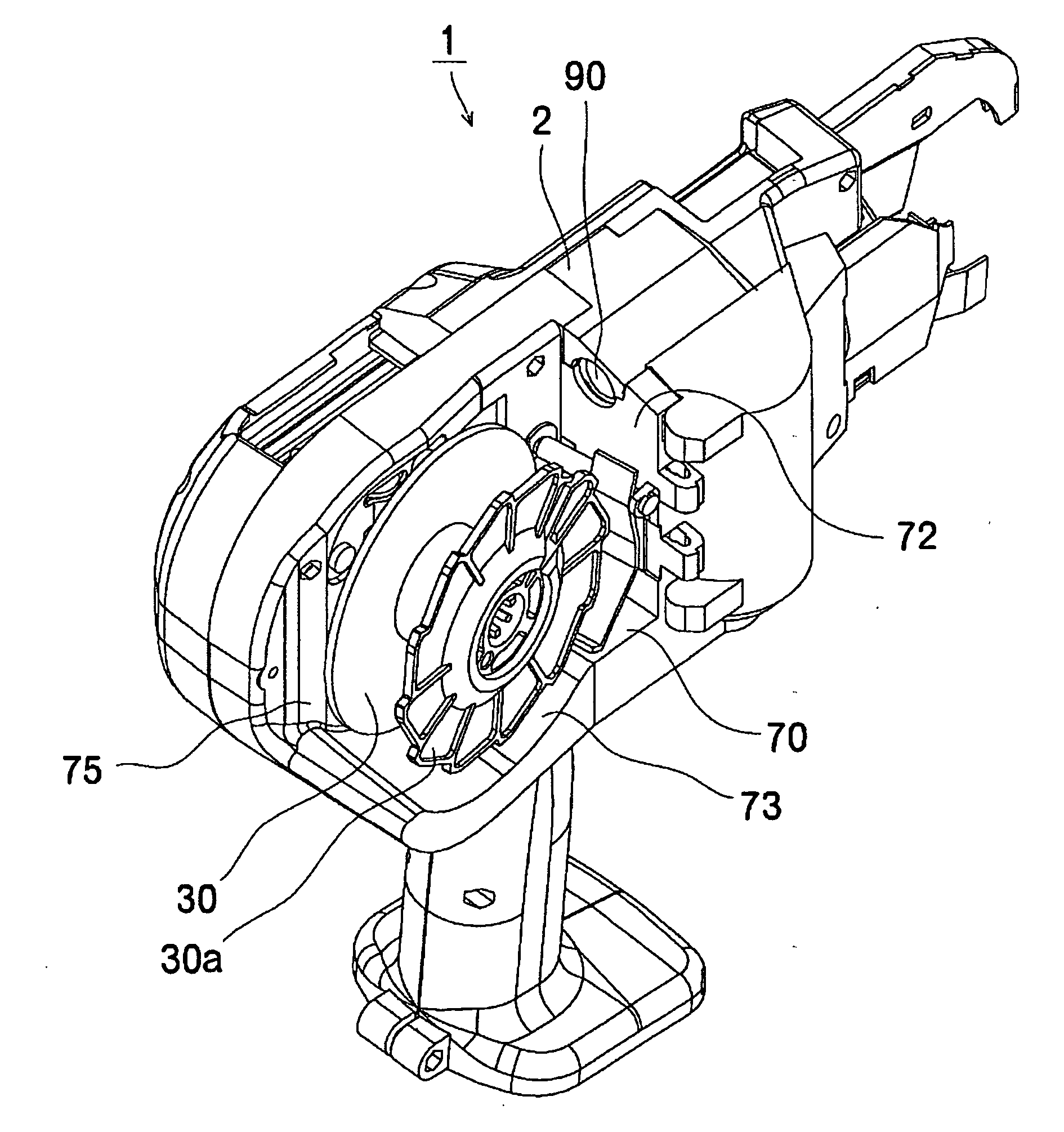
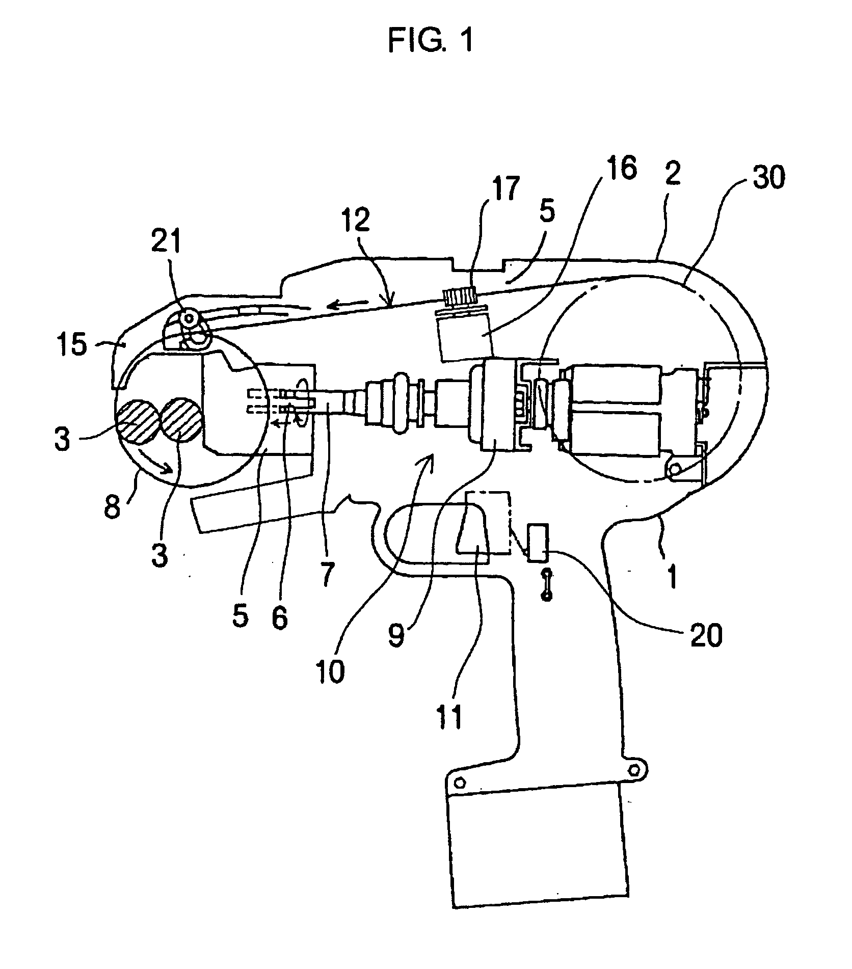
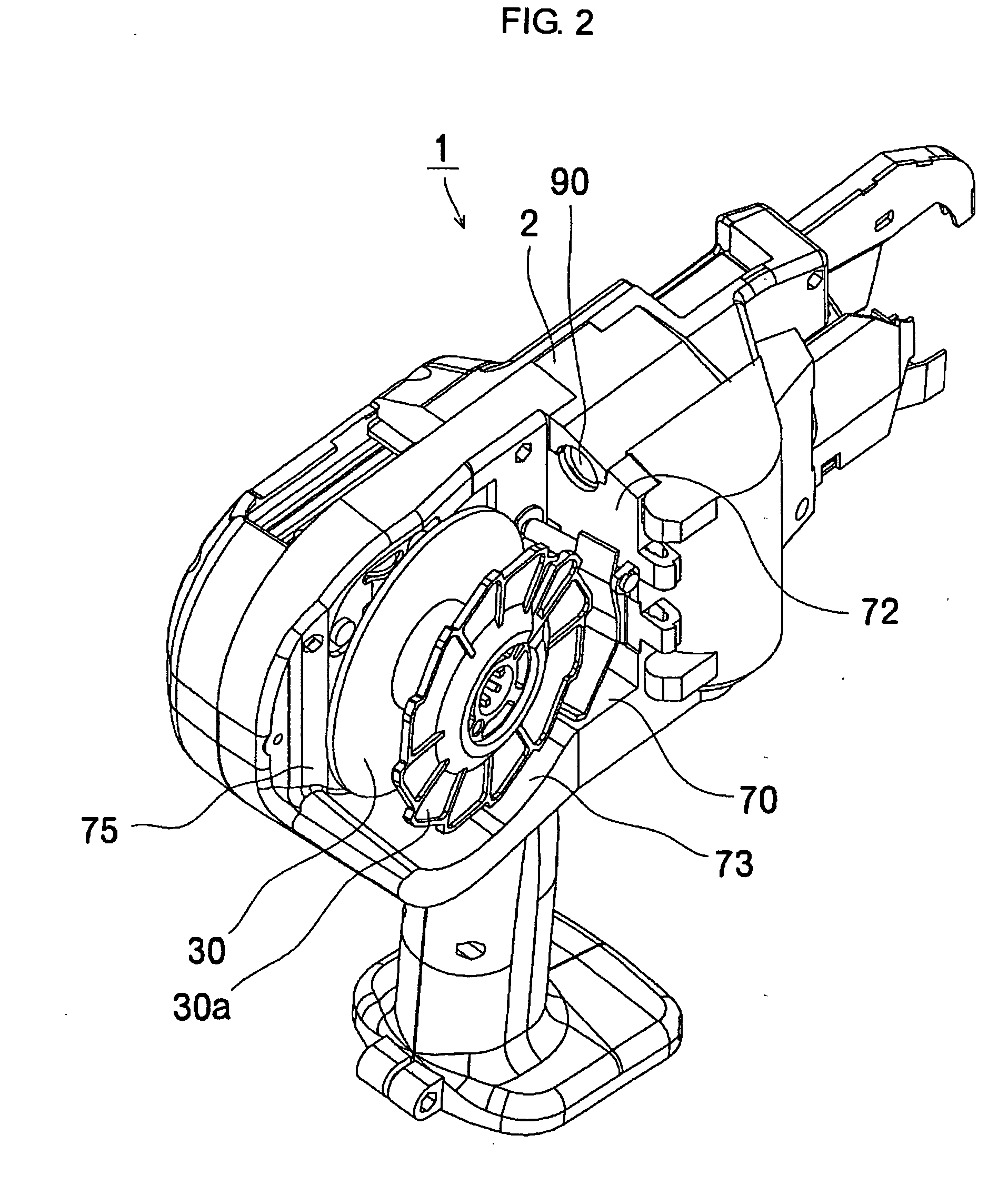
[0035] A reinforcing bar binder 1 includes a storing chamber 70 which is provided in a binder main body 2 and mounts a wire reel 30 around which a reinforcing-bar binding wire 8 is wound, as illustrated in FIG. 1 and FIG. 2. The reinforcing bar binder 1 feeds the wire 8 while rotating the wire reel 30, winds the wire 8 around a reinforcing bar 3 and then twists it to bind the reinforcing bar 3. In the storing chamber 70, there are provided a first detecting means 80 for detecting the amount of rotation of the aforementioned wire reel 30 and a second detecting means 25 for detecting the number of second to-be-detected portions 53 on the wire reel 30 during the amount of rotation detected by the first detecting means 80. In the binder maim body 2, there is provided a control means for controlling the amount of feeding of the wire 8 or the twisting torque on the wire 8, on the basis of the number of the second to-be-detected portions 53 detected by the second detecting means 25.

[0036]...


PUM

PropertyMeasurementUnit
twisting torqueaaaaaaaaaa
rotationaaaaaaaaaa
speedaaaaaaaaaa

Abstract

The present invention provides an inexpensive reinforcing bar binder capable of certainly identifying the type of a wire reel and automatically adjusting the amount of feeding of the wire wound around the wire reel or the twisting torque on the wire while having a simple construction.
A reinforcing bar binder 1 feeds a wire 8 while rotating a wire reel 30 mounted in a storing chamber 70 and binds a reinforcing bar 3. The storing chamber 70 is provided with a first detecting means 80 for detecting the amount of rotation of the wire reel 30 and a second detecting means 25 for detecting the number of second to-be detecting portions 53 on the wire reel 30 during the amount of rotation detected by the first detecting means 80. The binder main body 2 is provided with controlling means for controlling the amount of feeding of the wire 8 or the twisting torque on the wire 8 on the basis of the number of the second to-be-detected portions 53 detected by the second detecting means 25.

Description

TECHNICAL FIELD [0001] The present invention relates to a reinforcing bar binder capable of identifying the type of a wire reel and automatically adjusting the amount of feeding of a wire wound around the wire reel or the twisting torque on the wire, a wire reel used therewith and a method for identifying a wire reel. BACKGROUND ART [0002] In a conventional reinforcing bar binder, a wire reel around which a wire is wound is retained at the rear portion thereof and, when the switch is turned on and a trigger is manipulated, the wire is drawn out and fed forward from the wire reel through a wire feeding device, discharged in a loop shape from the tip end curved portion of a guide arm and wound onto a reinforcing bar and, thereafter, a twisting hook grips a portion of the loop and torsionally rotates to bind the reinforcing bar. As a configuration for automatically adjusting the wire twisting torque of such a reinforcing bar binder, there has been a configuration which provides display...

Claims


Application Information

Patent Timeline
Patent Type & Authority Applications(United States)
IPC IPC(8): B21F15/04B65B13/02B65B13/22B65B13/28E04G21/12
CPCB65B13/285Y10S242/912E04G21/122E04G21/123E04G21/12B65B13/28
Inventor NAGAOKA, TAKAHIROKUSAKARI, ICHIRO
Owner MAX CO LTD
Why Eureka
Try Eureka