Alarm lock

a technology of alarm locks and locks, applied in the field of locks, can solve the problems of not being able to remotely notify the owner of the lock, not being able to disclose the design of the lock, and not being able to communicate with cellular devices

Inactive Publication Date: 2006-12-28
SMITH WILLIAM
View PDF14 Cites 55 Cited by
  • Summary
  • Abstract
  • Description
  • Claims
  • Application Information

AI Technical Summary

Problems solved by technology

They fail to alert a person the lock is being tampered with or compromised.
It lacks the ability to remotely notify the owner of the lock if it is compromised.
It does not disclose a padlock design, nor the ability to remotely communicate with cellular devices.
It does not disclose a remote monitoring of the lock.
It does not disclose a mechanism for the remote monitoring of the lock....

Method used


Image

  • Alarm lock
  • Alarm lock
  • Alarm lock

Examples


Embodiment Construction

[0025] While describing the invention and its embodiments various terms will be used for the sake of clarity. These terms are intended to not only include the recited embodiments, but also all equivalents that perform substantially the same function, in substantially the same manner to achieve the same result.

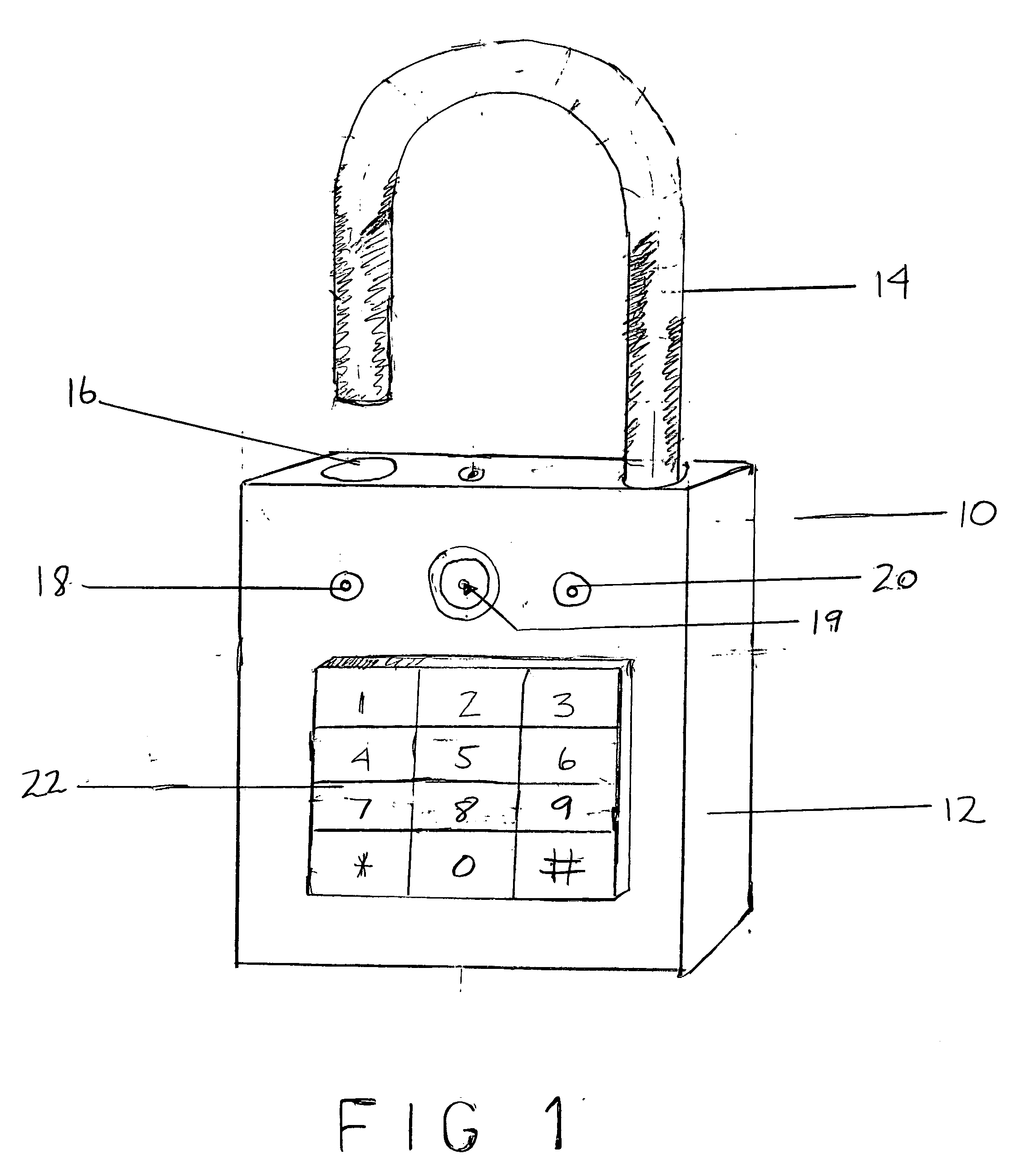
[0026]FIG. 1 shows a front view of a padlock 10. The padlock consists of a casing 12 and a cylindrically shaped shackle 14 and a hole 16 for receiving the shackle. The front of the padlock consists of a signal LED 18, a camera 19, battery indicator LED 20, a switch 49, and a keypad 22.

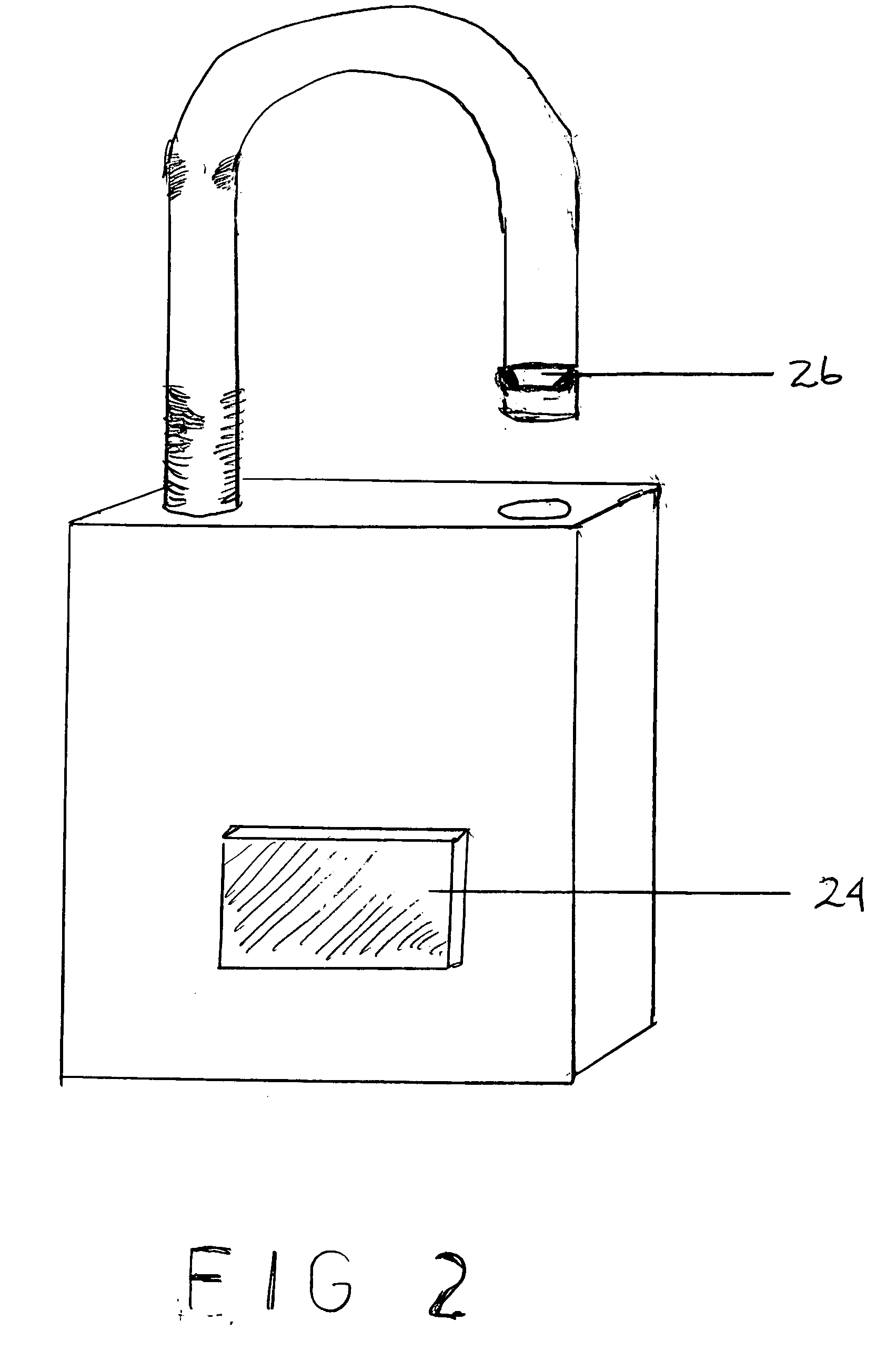
[0027]FIG. 2 is an opposite side view of the padlock 10 which incorporates a speaker 24 which may be of the standard magnetic paper cone variety or piezo electric. The shackle is shown in the open position with the notch 26 on the shackle.

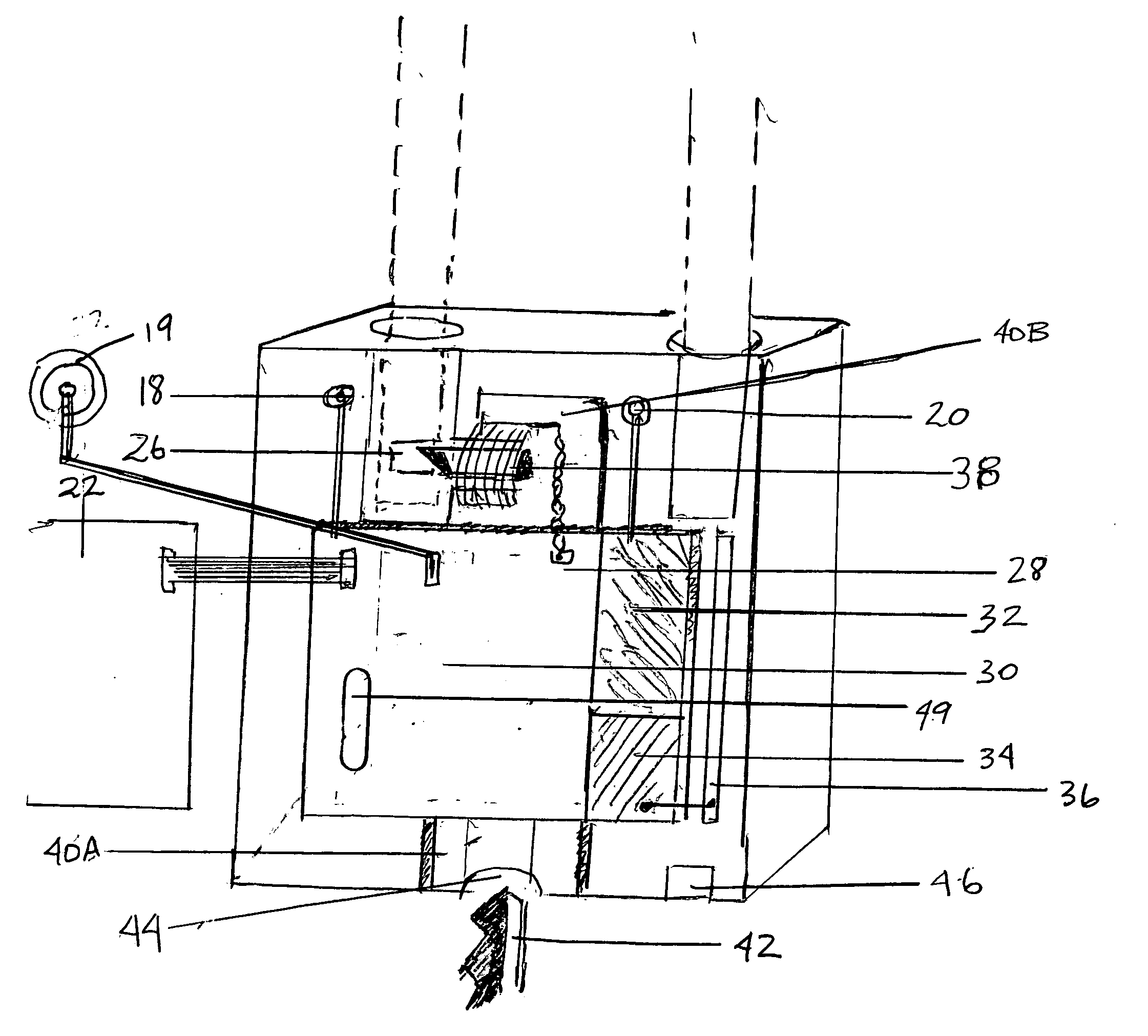
[0028]FIG. 3 is a front sectional view of the padlock 10 with the keypad 22 removed. The internal components consist of a circuit board 28 which contains the ...


PUM


Abstract

A electronic padlock is disclosed with remote control device. The electronic padlock has a tamper detection mechanism, a camera, and a speaker. The padlock can be remotely controlled using a remote device, such as a device similar to a garage door opener or a cell phone.

Description

BACKGROUND [0001] This invention relates to locks, specifically to locks that are used to secure lockers or bicycles. [0002] Locks are used to prevent unwanted people from obtaining access to areas without the permission of the owner. There are numerous designs for locks and their designs are well known in the arts. A padlock is one common design and is often used to secure lockers or used on chains to prevent bicycles from theft. [0003] Most padlocks are passive. They fail to alert a person the lock is being tampered with or compromised. Consequently a person rarely discovers if a lock has been broken until long after it has occurred. [0004] The present invention resolves that problem. It is an active device that alerts the owner of the lock by transmitting the status of the lock to the owner via a wireless channel. The lock incorporates an alarm feature to discourage tampering with the lock. In its preferred embodiment, the lock consists of a mechanism to open using a standard mec...

Claims


Application Information

Patent Timeline
IPC IPC(8): E05B67/24
CPCE05B47/06E05B67/24G07C2209/62G07C9/00142G07C9/00182E05B2047/0057Y10T70/461G07C9/33
Inventor SMITH, WILLIAM
Owner SMITH WILLIAM
Why Eureka
Try Eureka