Master-slave oriented two-way rf wireless lighting control system

a two-way radio frequency (rf) and control system technology, applied in pulse techniques, data switching networks, instruments, etc., can solve the problems of inflexible and costly modification of conventional lighting system configurations, inflexible installation cost and retrofit inflexibility, and limited range of conventional wired dali systems

Inactive Publication Date: 2006-03-02
KONINKLIJKE PHILIPS ELECTRONICS NV
View PDF12 Cites 449 Cited by
  • Summary
  • Abstract
  • Description
  • Claims
  • Application Information

AI Technical Summary

Benefits of technology

[0009] It is an object of the present teachings to provide a lighting control syste

Problems solved by technology

Conventional lighting system configurations are therefore inflexible and costly to modify.
However, retrofitting and/or modifying a lighting system for DALI requires extra control wires for connecting a control box to the lighting units' ballast.
Also, the conventionally wired DALI system has the disadvantage of added installation cost and retrofit inflexibility.
IR communication requires a line-of-sight between the IR linked devices and have a limited range based on ce

Method used


Image

  • Master-slave oriented two-way rf wireless lighting control system
  • Master-slave oriented two-way rf wireless lighting control system
  • Master-slave oriented two-way rf wireless lighting control system

Examples


Embodiment Construction

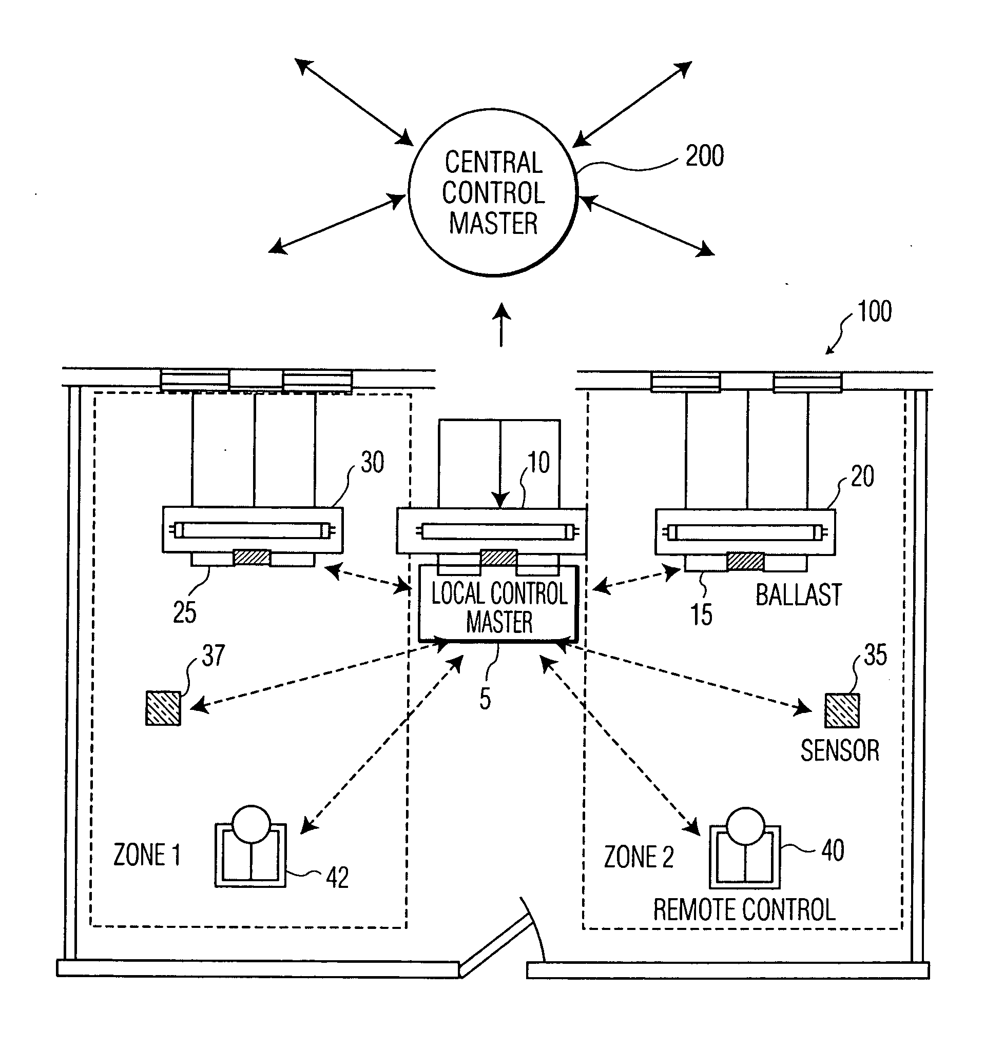
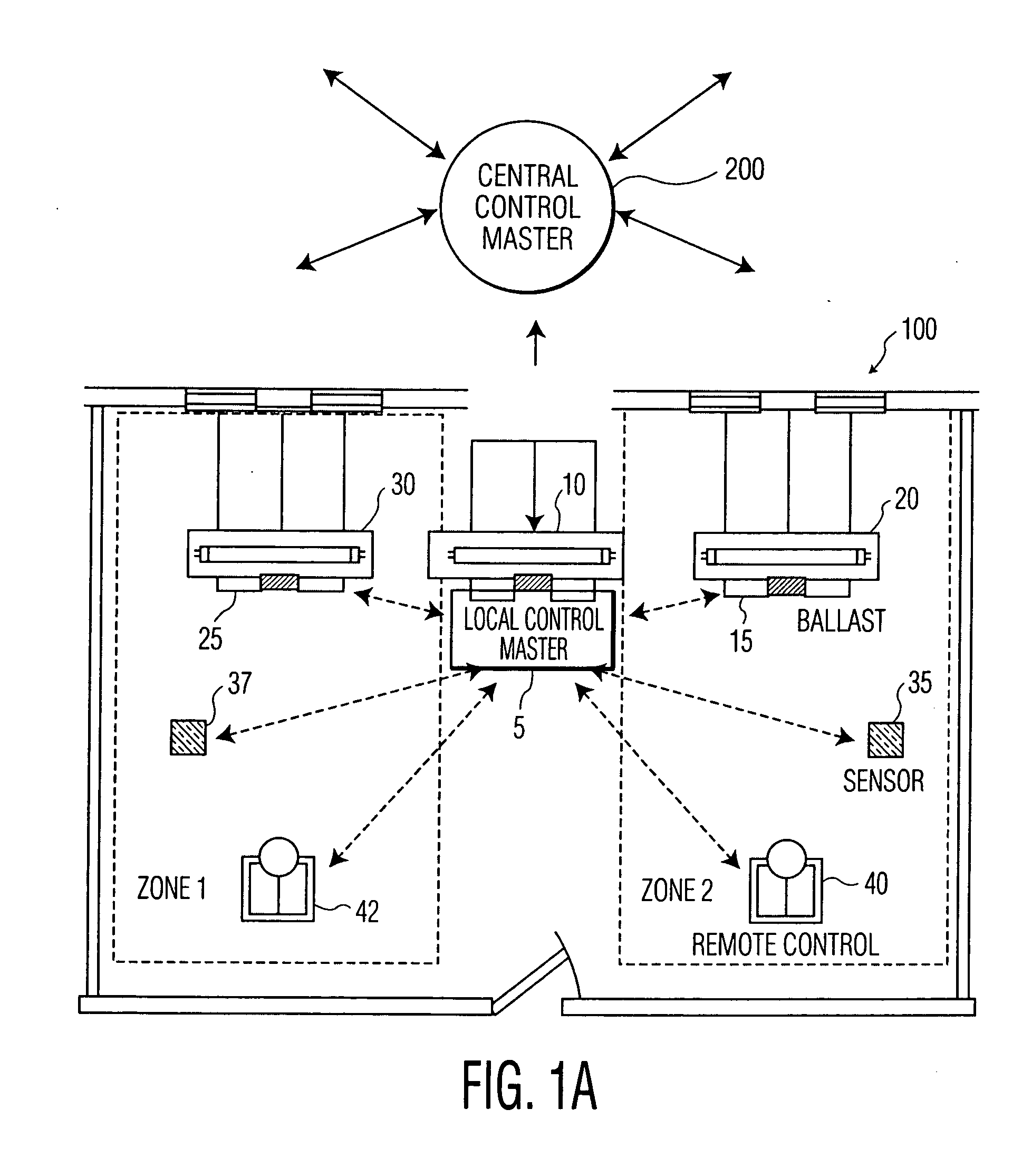
[0021] Referring to the figures, and in particular to FIG. 1A, there is depicted an exemplary representation of a lighting control network 100 in accordance with the teachings of the present invention. Note that while lighting control network 100 illustrates an exemplary deployment of the lighting control network of the present invention, it should be appreciated by those skilled in the art that the lighting control system of the present invention may be implemented and adapted to a variety of application environments.

[0022] In an aspect of the present invention, the lighting control system includes a master-slave oriented two-way (i.e., bi-directional) RF wireless lighting control network. Lighting control network 100 includes ballasts 5, 15, 25. Bach of the ballasts has a lighting control unit and is associated with a lighting unit controlled thereby. As shown, ballast 5 is associated with lighting unit 10, ballast 15 is associated with lighting unit 20, and ballast 25 is associa...


PUM


Abstract

A lighting control system network and method of providing same including a remote control unit having a RF signal transmitter and a RF receiver and a number of lighting control units, each of the lighting control units having a RF signal transmitter, a RF receiver, and a lighting unit associated therewith. The remote control unit and the lighting control units are configured in a master-slave oriented network. One of the lighting control units is configured as a master in the network and the remaining lighting control units and the remote control unit are configured as slaves in the network. The lighting control units and the remote control units communicate bi-directionally with each other over RF wireless links. The network may include sensors for detecting an environmental or system parameter. Multiple instances of the lighting control network may be interfaced together to form a building-wide network.

Description

BACKGROUND OF THE INVENTION [0001] 1. Field of the Invention [0002] The present invention relates to a lighting control system, and particularly to a master-slave oriented two-way radio frequency (RF) lighting control system. [0003] 2. Description of the Related Art [0004] Conventional building lighting systems, both residential and commercial, include numerous lighting units controlled by wall switches interconnected together by electrical wiring. Any changes and modifications to the lighting system are either constrained by the electrical wiring or require re-wiring of the lighting system. Conventional lighting system configurations are therefore inflexible and costly to modify. [0005] Lighting system control configurations range from simple to complex. In one of the simplest control schemes, lights are turned on / off by dedicated wall switches located, typically, in the same room as the lights controlled by the wall mounted switches. Additionally, wall dimmers may be used to contr...

Claims


Application Information

Patent Timeline
IPC IPC(8): G06F13/42H04Q9/00H05B37/02
CPCH04L12/2803H04L12/282H04L12/2827H04L29/12254H05B37/0272H04L2012/2841H04L2012/285H05B37/0245H04L61/2038H05B47/175H05B47/19H04L61/5038
Inventor WANG, LING
Owner KONINKLIJKE PHILIPS ELECTRONICS NV
Why Eureka
Try Eureka