Patch panel for mounting on a wall or in a subrack

Inactive Publication Date: 2006-12-28
UNIFY GMBH & CO KG
View PDF7 Cites 10 Cited by
  • Summary
  • Abstract
  • Description
  • Claims
  • Application Information

AI Technical Summary

Benefits of technology

[0007] An object of the invention is to specify a patch panel so as to make it equally well suited f

Problems solved by technology

In addition there also are simple configurations in which it is too expensive to use a subrack.
Different housing constructions or a

Method used


Image

  • Patch panel for mounting on a wall or in a subrack
  • Patch panel for mounting on a wall or in a subrack
  • Patch panel for mounting on a wall or in a subrack

Examples


Embodiment Construction

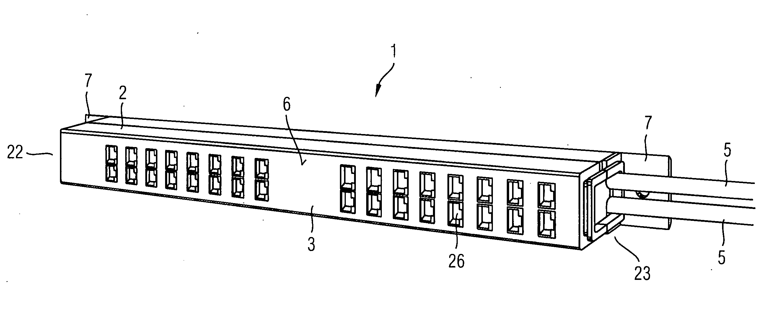
[0027]FIG. 1 shows a perspective view of the inventive patch panel 1 which is set up for wall mounting. For routing of data waiting on lines in incoming cables 5 the front panel 3 of the patch panel 1 is embodied as a jumpering panel 6. The jumpering panel 6 consists of connection jacks 26 arranged in rows the connection jacks are embodied in the exemplary embodiment as RJ-45 sockets into which RJ-45 plug-in devices of outgoing cables which are not shown in greater detail in FIG. 1 can be plugged. On each end face 22 and 23 of the housing part 2 there is a wall-mounting bracket 7 provided which is pushed on from the rear. On each angle bracket 7 holes for screws are provided, through which the patch panel can be mounted on a wall.

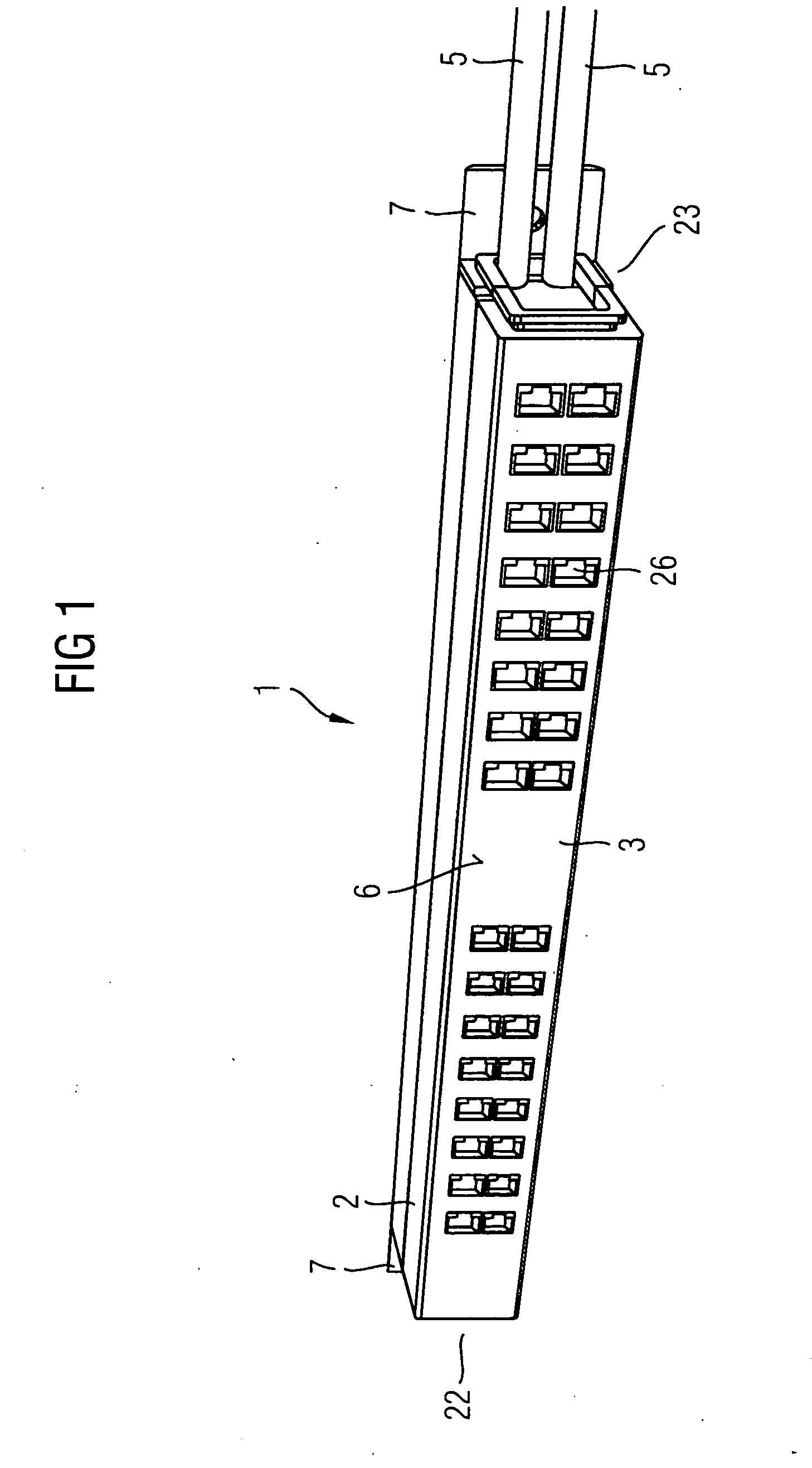
[0028] For mounting in a subrack the angle brackets 7 are pushed on from the front, as shown in the perspective view of FIG. 2.

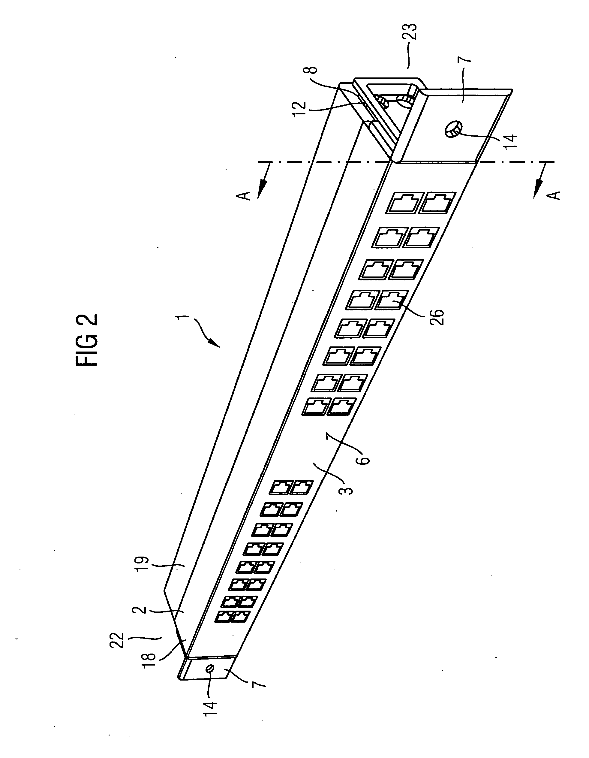
[0029]FIG. 3 shows the patch panel 1 in accordance with the invention in an exploded view before assembly for mounting in a subr...


PUM


Abstract

The invention relates to a patch panel for mounting on a wall or in a subrack, comprising a housing part, which can be mounted on ends located on respective faces by means of angle brackets and which has a front cover provided in the form of a patch panel for routing data waiting on lines of an incoming cable to lines that can be connected via connecting devices on the front cover. An angle bracket is provided on each end and has a fork-type spring detent that can be inserted at the front and rear into guide slots, which are provided for insertably accommodating the fork-type spring detent on the ends that are situated on opposite sidewalls of the housing part, and the fork-type spring detent can be snapped in by means of corresponding detent means.

Description

CROSS REFERENCE TO RELATED APPLICATIONS [0001] This application is the US National Stage of International Application No. PCT / EP2004 / 001964, filed Feb. 27, 2004 and claims the benefit thereof. The International Application claims the benefits of German application No. 10313358.5, filed Mar. 25, 2003. The International Application and the German application are incorporated by reference herein in their entirety.FIELD OF THE INVENTION [0002] The invention relates to a patch panel for mounting on a wall or in a subrack, with a housing part which can be mounted by means of angle brackets on its end faces and featuring a front panel which is embodied as a panel for routing data waiting on lines of an incoming cable to lines that can be connected to the front panel by connecting devices. BACKGROUND OF THE INVENTION [0003] A patch panel is a panel which is used for connecting, distributing and routing data connections. The front panel of a patch panel contains the connection jacks for outg...

Claims


Application Information

Patent Timeline
IPC IPC(8): H02B1/00H04Q1/14
CPCH04Q1/13H04Q1/02H04Q1/14
Inventor VERDING, MARKUS
Owner UNIFY GMBH & CO KG
Why Eureka
Try Eureka