Ratchet wrench

A technology of ratchet wrench and ratchet, which is applied in the field of ratchet wrench, which can solve the problems of increased production cost and assembly burden, high cost, complex structure of ratchet wrench, etc., and achieve the effect of simplifying the overall structure and facilitating manufacturing and assembly

Inactive Publication Date: 2016-02-17
STANLEY CHIRO INT
View PDF9 Cites 9 Cited by
  • Summary
  • Abstract
  • Description
  • Claims
  • Application Information

AI Technical Summary

Problems solved by technology

[0003] However, the structure of this kind of ratchet wrench is relatively complicated, which will increase the burden on production cost and as

Method used


Image

  • Ratchet wrench
  • Ratchet wrench
  • Ratchet wrench

Examples


Example Embodiment

[0022] Hereinafter, preferred embodiments will be used to illustrate the structural features and expected effects of the present invention, but they are not intended to limit the scope of protection of the present invention, and are described first.

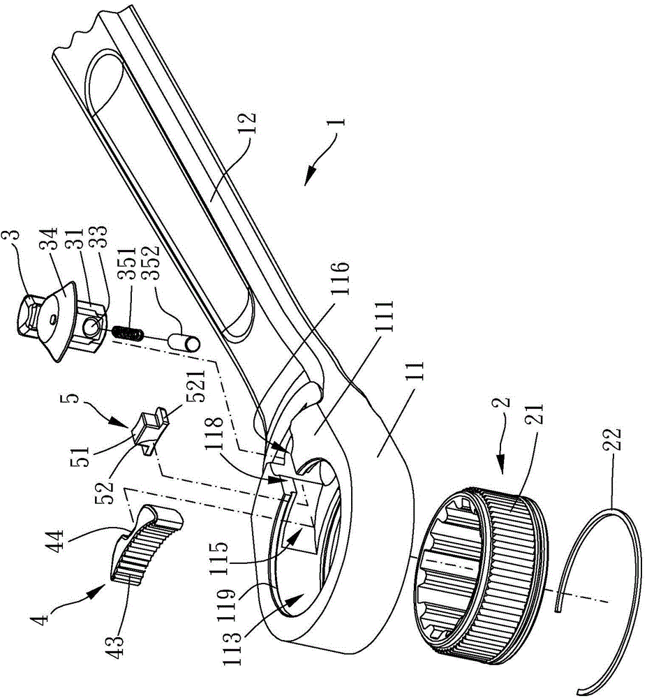
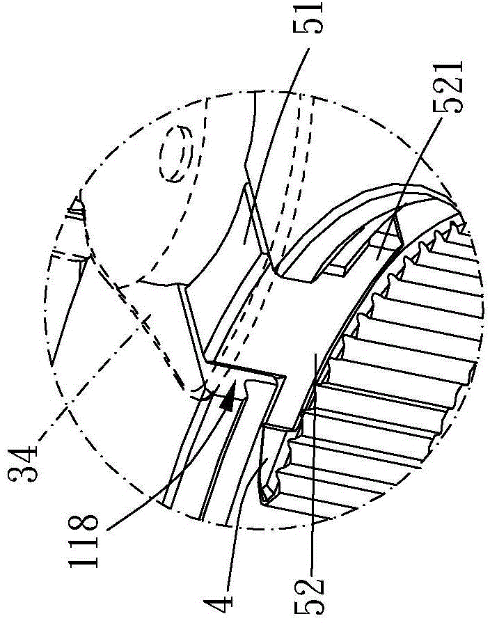
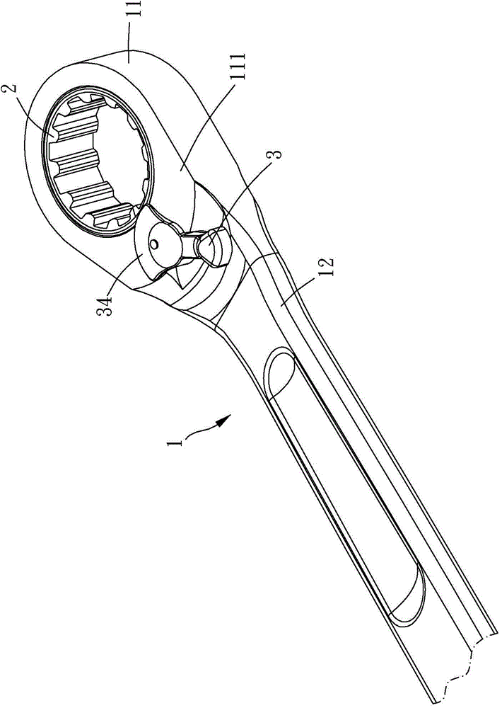
[0023] Please refer to Figure 1 to Figure 4 , The ratchet wrench of the present invention includes a body 1, a ratchet wheel 2, a control member 3, a latch member 4 and a fixing member 5.

[0024] The body 1 has a head 11 and a handle 12, the head 11 has a first surface 111, a second surface 112, an accommodating hole 113, and an accommodating groove located on the inner surface of the accommodating hole 113 115 and an assembling hole 116, the accommodating hole 113 penetrates the first surface 111 and the second surface 112, the first surface 111 is provided with the assembling hole 116, and the accommodating groove 115 is connected to the accommodating hole 113 and Between the assembling holes 116, between the assembling hole 116 ...


PUM


Abstract

A ratchet wrench is provided, including a main body, a ratchet, a controlling member, a restriction member and a fixing member. A head portion of the main body has a first face, a second face, a receiving hole, a receiving slot disposed in an inner surface of the receiving hole and an assembling hole. A through hole communicates the assembling hole and the receiving hole. The ratchet is rotatably disposed in the receiving hole. An assembling portion of the controlling member is rotatably inserted in the assembling hole. The restriction member is movably disposed in the receiving slot. The fixing member is disposed in the through hole, and the fixing member is abutted against the controlling member to restrict the assembling member to stay in the assembling hole. Whereby, it is convenient to manufacture and assemble the ratchet.

Description

technical field [0001] The invention relates to a tool, in particular to a ratchet wrench. Background technique [0002] Existing ratchet wrench, as described in the patent No. M462646 of Taiwan, China, mainly has a ratchet part formed on a wrench body, and the ratchet part is provided with an actuating port and a round hole, and a ratchet groove is communicated between them, and a control part is formed by a disc. There is a handle body extending from one end of the disc, and a block is formed at the other end. A U-shaped seat is formed on the top of the block, and a spring is installed at the U-shaped seat, and a limiting gap is recessed between the disc part and the U-shaped seat. , the control part is installed in the round hole, and the U-shaped seat of the control part faces the ratchet groove. One end of the ratchet part is formed with arc-shaped teeth, and the other end is provided with a limiting part. A cylinder protrudes from the limiting part. The ratchet part i...

Claims


Application Information

Patent Timeline
IPC IPC(8): B25B13/46
Inventor 周信宏
Owner STANLEY CHIRO INT
Why Eureka
Try Eureka