Shaft testing device capable of exerting two-stage combined tension-torsion loading simultaneously

A test device and composite load technology, which is applied in the direction of measuring devices, testing of mechanical components, testing of machine/structural components, etc., can solve problems such as inconsistency of force conditions and inability to simulate turbine shaft loads, and achieve simple manufacturing and assembly. Experiment with full-featured, low-cost effects

Active Publication Date: 2014-01-22
CHENGDU ENGINE GROUP
View PDF7 Cites 9 Cited by
  • Summary
  • Abstract
  • Description
  • Claims
  • Application Information

AI Technical Summary

Problems solved by technology

[0004] The present invention aims at the deficiencies of the turboshaft tester in the prior art. The purpose of the present invention is to provide a shaft test device with a new structure that can simultaneously apply two-stage tensile-torsion compound loads, so as

Method used


Image

  • Shaft testing device capable of exerting two-stage combined tension-torsion loading simultaneously
  • Shaft testing device capable of exerting two-stage combined tension-torsion loading simultaneously
  • Shaft testing device capable of exerting two-stage combined tension-torsion loading simultaneously

Examples


Example Embodiment

[0024] Example 1

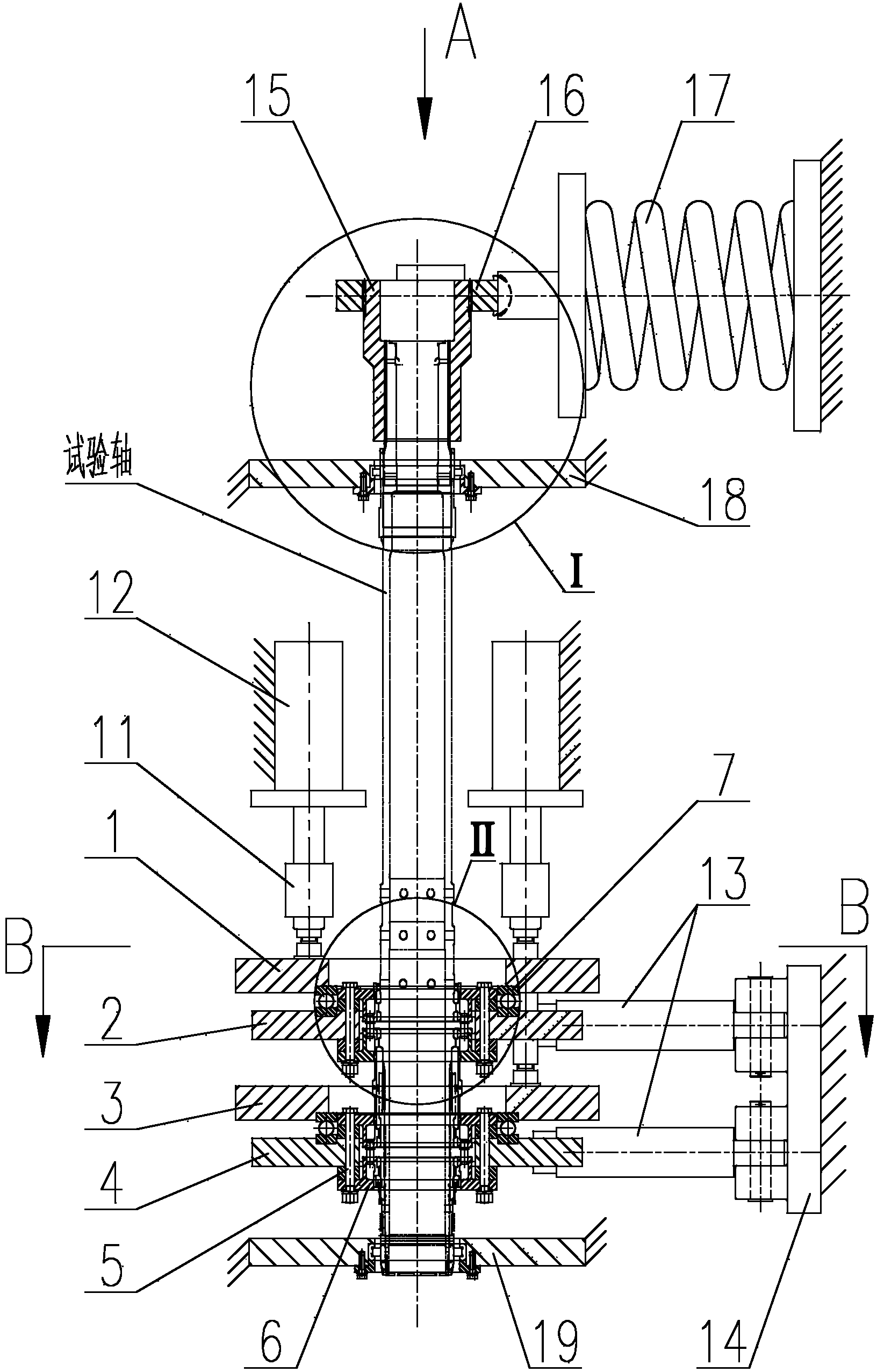
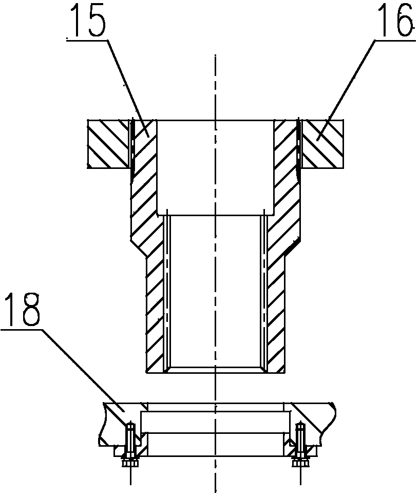
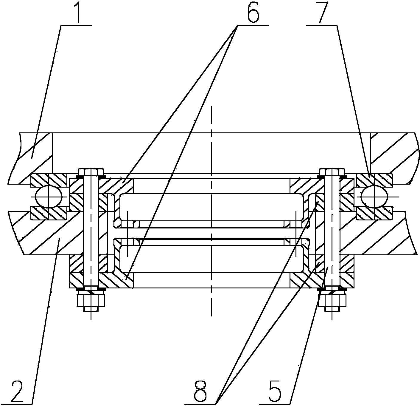
[0025] The shaft test device of this embodiment that can simultaneously apply two-stage tension and torsion composite load, its structure is as attached figure 1 Attached Image 6 As shown, the tested shaft is the turbine shaft of a certain type of aero engine. The specific structure of this test device is as follows.

[0026] 1. The overall structure of this test device is attached figure 1 As shown, it is composed of a device frame, a first-stage tensile torsion load loading module, a second-stage tensile torsional load loading module, a reverse torque load loading module, and a test shaft positioning device installed on the rack. The test device is a vertical structure as a whole. The torque loading cylinder 13 in the first-stage tensile-torsional load loading module and the second-stage tensile-torsional load loading module, and the return spring assembly 17 in the anti-torque load loading module are all set horizontally. The axial force loading cylinders 1...


PUM


Abstract

The invention discloses a shaft testing device capable of exerting two-stage combined tension-torsion loading simultaneously. The shaft testing device mainly comprises a rack as well as a first-stage tension-torsion loading load module, a second-stage tension-torsion loading load module and a reactive torque loading load module which are installed on the rack. Each of the first-stage tension-torsion loading load module and the second-stage tension-torsion loading load module comprises torque load oil cylinders, a torque bearing disk, axial force load oil cylinders and an axial force bearing disk, wherein the torque load oil cylinders are arranged in a reverse symmetry manner, the torque bearing disk is fixed with one end of a to-be-tested shaft, the axial force load oil cylinders are arranged symmetrically, a piston of each torque load oil cylinder is hinged to each torque bearing disk through a torque load connecting component, a piston of each axial force load oil cylinder acts on each axial force bearing disk through an axial force load connecting component, and each axial force bearing disk is axially connected with each torque bearing disk through a thrust bearing. The reactive torque loading load module comprises return spring components and a reactive torque bearing disk, wherein the return spring components are arranged in a reverse symmetry manner, and the reactive torque bearing disk is fixed with the other end of the to-be-tested shaft.

Description

technical field [0001] The invention relates to a life-defining test device for a rotating shaft, in particular to a life-defining test device for simultaneously applying axial force and torque load to an aeroengine turbine shaft. Background technique [0002] The turboshaft is an important part of the engine. It bears a lot of loads during flight, and since there are many stress-concentrated parts such as steps and holes that are prone to crack initiation on the turbine shaft, once the turbine shaft cracks initiate during flight, fatal shaft failure may occur. Since the gyroscopic moment and maneuvering moment of the turbine shaft in flight cannot be simulated on the engine test bench, the ground test vehicle cannot simulate the maneuvering flight load of the turbine shaft, and the life test by air flight is costly and extremely dangerous. Therefore, it is the key to solve the shaft faults to build a test device that can fully simulate the various loads that the turbine sh...

Claims


Application Information

Patent Timeline
IPC IPC(8): G01M13/00
Inventor 刘建周军张开方刁明宣冯晓鹏方滨刘鹏宇
Owner CHENGDU ENGINE GROUP
Why Eureka
Try Eureka