A Modular Integrated Brake Performance Test Bench

A test bench and modular technology, applied in the direction of railway vehicle testing, etc., can solve problems such as single function, and achieve the effect of saving space, compact structure and optimized structure

Active Publication Date: 2021-03-19
SOUTHWEST JIAOTONG UNIV
View PDF16 Cites 0 Cited by
  • Summary
  • Abstract
  • Description
  • Claims
  • Application Information

AI Technical Summary

Problems solved by technology

[0005] Aiming at the problem that the friction brake test bench in the prior art can only be used for one type of brake and has a single function, the present invention provides a modularized comprehensive braking performance test bench. The high integration of dynamic brakes, tread brakes and full-size disc brakes of automobiles can be replaced according to actual test needs without additional development and production of corresponding test benches

Method used


Image

  • A Modular Integrated Brake Performance Test Bench
  • A Modular Integrated Brake Performance Test Bench
  • A Modular Integrated Brake Performance Test Bench

Examples


Embodiment 1

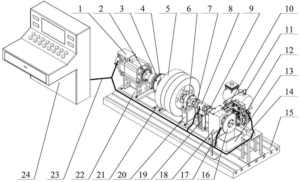
[0053] A modularized comprehensive braking performance test bench is installed in a laboratory. First, prefabricate a foundation of suitable size and depth in the laboratory, completely fix the test bench base 15 and the foundation, and install the brake module loading seat 18, torque sensor mounting table 19, bearing seat II mounting table 20, and bearing seat I through bolts. Table 21, motor installation table 22 are fixedly connected with test bench base 15, the output shaft of motor 1 is connected with clutch 3 through clutch motor coupling sleeve 2, power transmission is realized through bearing seat I4 and flywheel group 5, and flywheel group 5 supports Between the bearing seat I4 and the bearing seat II6, the output end of the rotating shaft of the flywheel group 5 is connected to the rotating shaft of the torque sensor 8 through the coupling I7. The disc I 16 is connected with a rotating shaft, and the rotating shaft is installed on the brake module loading seat 18 thr...

Embodiment 2

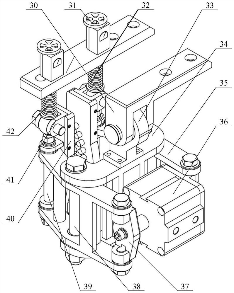
[0061] The structure of this embodiment is basically the same as that of Embodiment 1, the difference is that the train disc caliper brake module is changed to a single friction block caliper brake module, and the single friction block caliper brake module includes a cylinder II48 and is used to connect with the brake module The support frame 46 connected to the loading seat 18, the support frame 46 is connected with a support arm 45, each of the two ends of the support arm 45 is hinged with a curved arm 47, and one end of the two curved arms 47 is connected to the cylinder II48 respectively. Both ends are hinged, and the other ends of the two curved arms 47 are respectively hinged with a friction block unit 44 for providing braking force to the side of the brake disc.

[0062] When carrying out the train braking performance test of a single friction block under different shapes, the single friction block caliper brake module assembled by the friction block unit 44, the support...

Embodiment 3

[0065] The structure of this embodiment is basically the same as that of Embodiment 1, the difference is that the brake module of the train disc caliper is changed to a tread brake module, and the tread brake module includes a tread brake mounting seat 49 for connecting with the brake module loading seat 18 , the tread brake mount 49 is fixedly connected with a cylinder III51 and a tread slant support 50, the lower end of the tread slant support 50 is hinged with an intermediate rod 52, and the extension direction of the cylinder rod of the cylinder III 51 is vertically downward Set, the end of the cylinder rod is hinged with the middle rod 52, and the end of the middle rod 52 is connected with a tread brake friction block 53, and the tread oblique support 50 and the tread brake friction block 53 are respectively located on the sides of the cylinder rod. On both sides, the tread brake friction block 53 is located above the brake disc.

[0066] When carrying out the tread brake...


PUM


Abstract

The invention belongs to the technical field of friction braking and particularly relates to a modularized comprehensive brake performance testing bench. Aiming at the problem that a friction brakingtest bench in the prior art only aims at one type of brakes and is single in function, the technical scheme includes that the modularized comprehensive brake performance testing bench comprises a testing bench base, and a driving device, a rotating shaft, a flywheel group and a detection device are arranged on the testing bench base; the testing bench base is further provided with a brake module loading seat, a brake disc is arranged at the tail end of the rotating shaft, and one end, with the brake disc, of the rotating shaft is connected with the brake module loading seat through a bearing;the brake module loading seat is provided with a plurality of mounting holes for mounting of brake modules; a friction brake module is one of a train disc caliper brake module, a single-friction-blockcaliper brake module, a tread brake module or a full-size automobile brake module. The modularized comprehensive brake performance testing bench is applicable to researches on scientific problems ofbrake disc / plate contact interface vibration noise, wear law, friction heat distribution and the like in a vehicle braking process.

Description

technical field [0001] The invention belongs to the technical field of friction braking, and in particular relates to a modular comprehensive braking performance test bench. Background technique [0002] As the key test equipment in the field of vehicle friction braking, the braking performance test bench is mainly used to study the vibration noise of the contact interface of the brake disc / plate during the braking process of the vehicle, its wear law and friction heat distribution, etc. It is used for various types of brakes. The optimal braking performance provides accurate test data support. Friction braking can be applied in normal braking and emergency braking, and it is also the last guarantee for safe parking. With the rapid development of the national economy, the means of transport are developing towards high speed, especially in the field of electrified trains, constantly breaking through the maximum operating speed. On the other hand, the national and social lev...

Claims


Application Information

Patent Timeline
Patent Type & Authority Patents(China)
IPC IPC(8): G01M17/08
Inventor 莫继良项载毓范志勇唐斌吴元科朱旻昊周仲荣
Owner SOUTHWEST JIAOTONG UNIV
Why Eureka
Try Eureka