Microphone and headphone assembly for the ear

a headphone and microphone technology, applied in the direction of deaf-aid sets, electrical transducers, transducer details, etc., can solve the problems of headphones in the traditional way, the microphone is not concealed, and the equipment that sticks out in front of the face damage, so as to reduce or eliminate unnecessary wire slack, the effect of effective concealmen

Inactive Publication Date: 2007-01-04
NAM DAEHWI
View PDF27 Cites 30 Cited by
  • Summary
  • Abstract
  • Description
  • Claims
  • Application Information

AI Technical Summary

Benefits of technology

[0033] (17) to provide such an assembly wherein the microphone of the assembly does not pick up unwanted sound waves from outside the human body; and
[0034] (18) to provide such an assembly that c

Problems solved by technology

While placement of the microphone in front of the mouth may be perfectly suitable for many situations, such placement has certain drawbacks in other situations.
One such drawback stems from the mere fact that the microphone is not concealed.
Similarly, special operations or other soldiers on the battlefield have a strong need to be able to communicate even during explosions or other chaotic battle conditions, which damage equipment that stick out in front of the face.
Another drawback stems from the fact that using headphones in the traditional way requires transmitting sound vibrations from the mouth to a point outside the mouth where the microphone is located.
Even though the microphone may be only a few centimeters from the mouth, the fact that the sound waves travel that distance outside the body leaves them open to noise interference from other points outside the body.
For example, in a chaotic and noisy combat situation, the transmission to the microphone picks up all the noise around the soldier.
Another drawback is that placing the microphone in that location may obstruct visibility of the face of the user.
That can be unseemly for reasons of appearanc

Method used


Image

  • Microphone and headphone assembly for the ear
  • Microphone and headphone assembly for the ear
  • Microphone and headphone assembly for the ear

Examples


Embodiment Construction

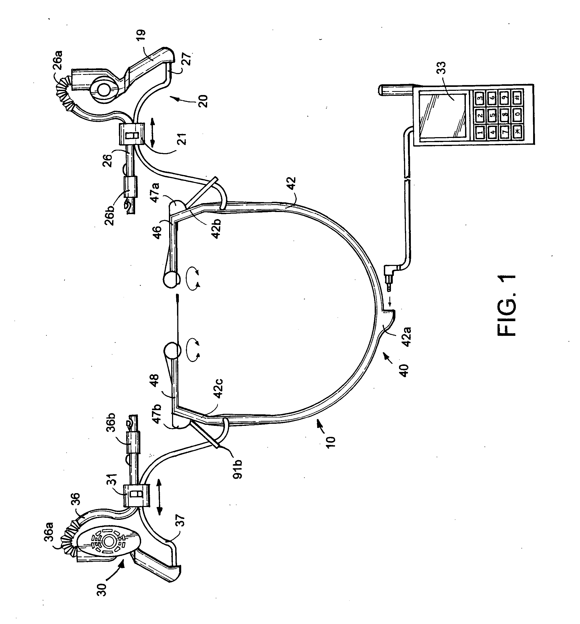
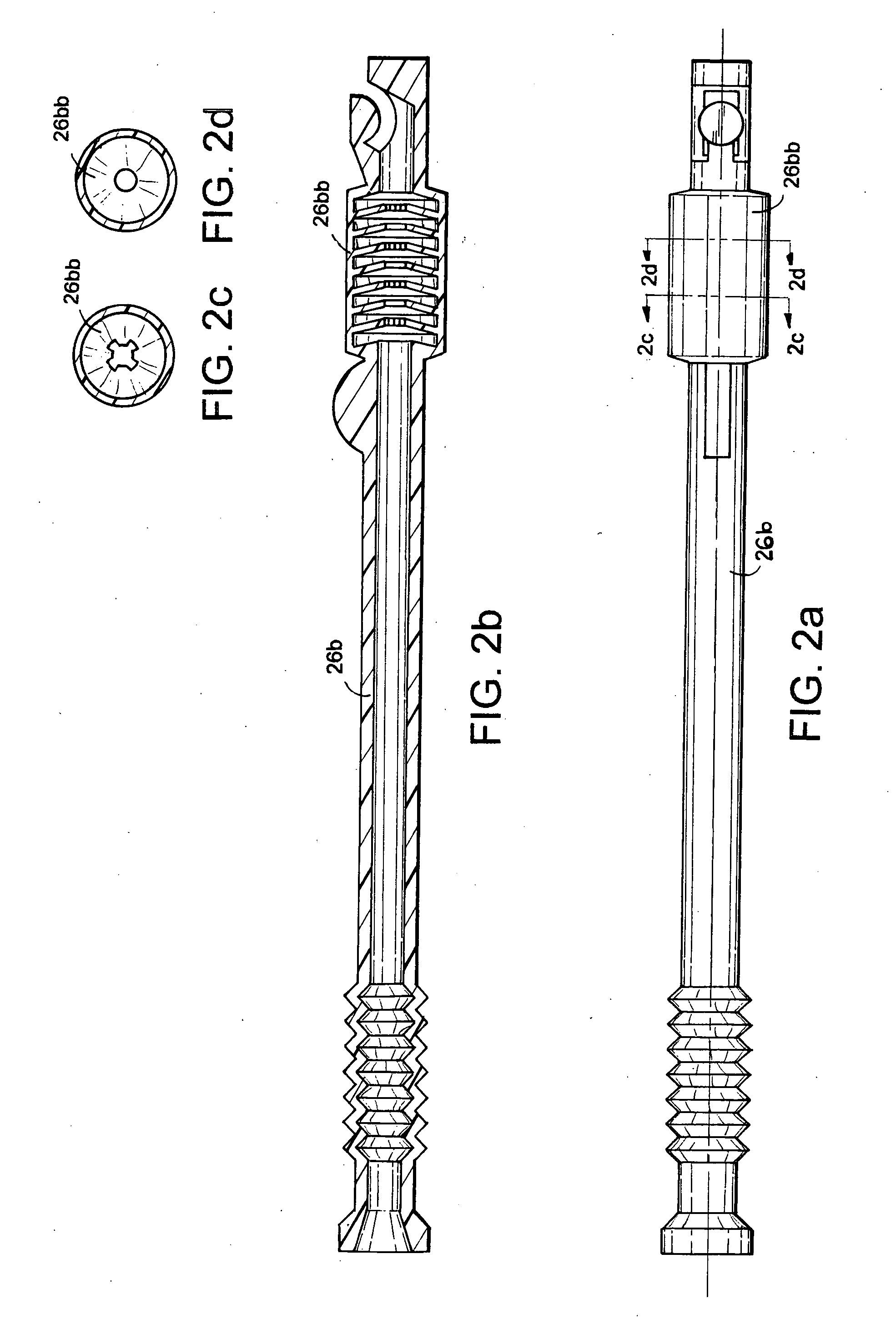
[0054] The apparatus of the present invention will now be illustrated by reference to the accompanying drawings. The assembly of the present invention has been assigned reference numeral 10 Other elements of the assembly have been assigned the reference numerals referred to below.

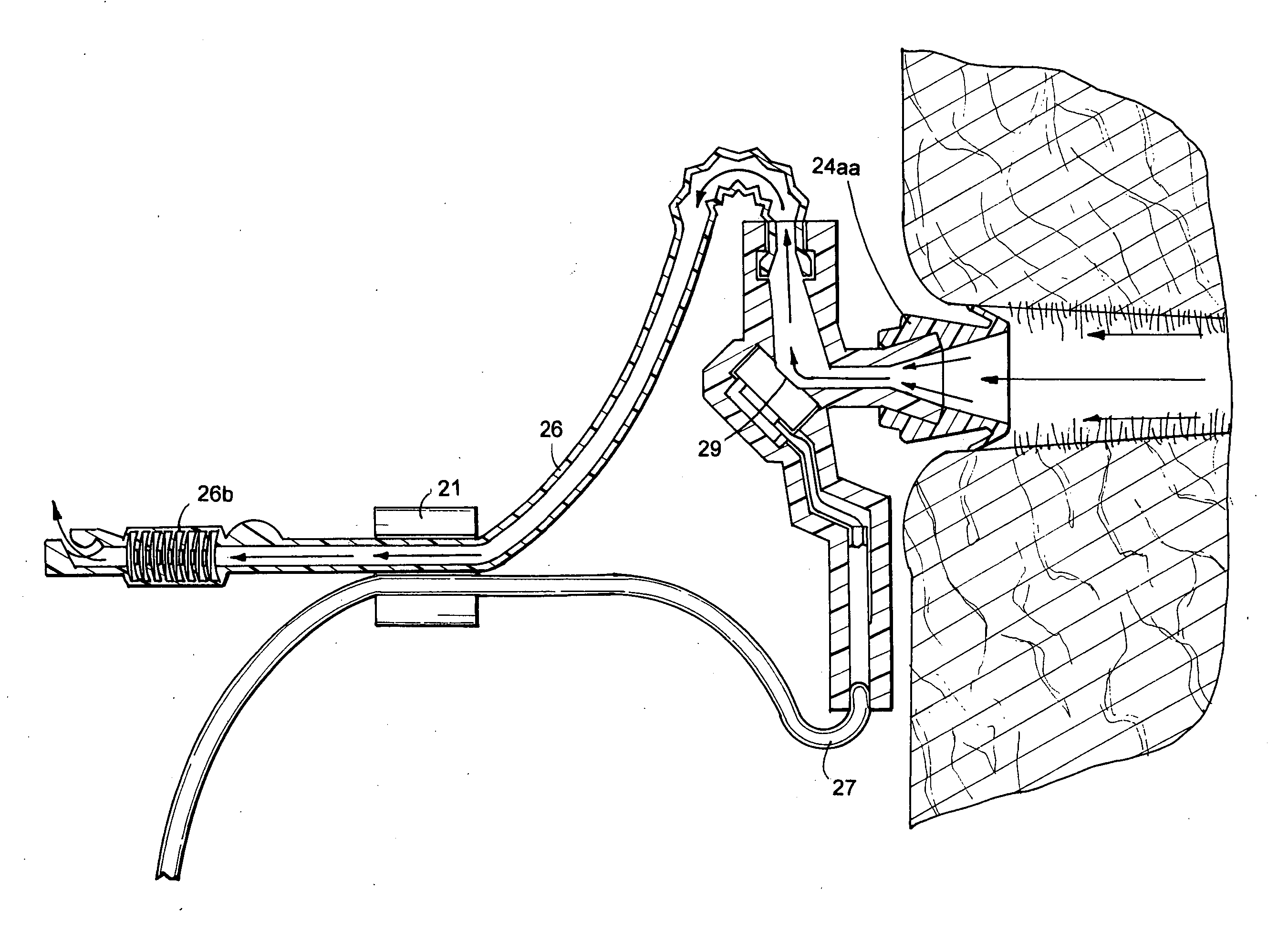
[0055] As seen from FIGS. 1-8c, the present invention is a headphone and microphone assembly 10, also called an earphone and microphone assembly, and is designed to plug into a communication device such as a cellular telephone. The assembly 10 overall comprises a microphone unit 20, a headphone unit 30 and a neck attachment unit 40, the latter also referred to as a holder unit 40. As will be appreciated, microphone unit 20 comprises an open system whereas headphone unit comprises both an open system and a closed system.

[0056] Microphone unit 20 is designed to fit into and be placed into a first ear of a user. This does not mean necessarily that the entire microphone unit 20 fits inside the ear of the user...


PUM


Abstract

A microphone unit positioned in one ear and including a microphone, noise cancellation tube and ear tube, and a headphone unit positioned in the other ear, together with a neck attachment unit around the wearer's neck form an assembly for connecting to a communication device such as a cellular telephone while jogging or exercising. The microphone unit has a first movable joint for holding the first wire and the first noise cancellation tube and for controlling a length of slack of the first wire. The headphone unit includes an earphone cap, a second noise cancellation tube and a second movable joint for holding the second wire and second noise cancellation tube and for controlling a length of slack of the second wire. The neck attachment unit comprises a C-shaped holder that holds the first wire and the second wire and includes two swivel arms as grippers.

Description

FIELD OF THE INVENTION [0001] The field of this invention is assemblies of units that include a microphone and a headphone for use with cellular telephones, and more particularly, such assemblies that allow for positioning of the microphone unit in the ear of a user. BACKGROUND OF THE INVENTION AND DISCUSSION OF THE PRIOR ART [0002] With the popularity and ubiquity of cellular telephones, various versions of cellular telephone assemblies came into being whereby the user can speak on the cellular telephone without having to hold the telephone and speak into a microphone incorporated into the housing of the phone; rather the microphone is outside the phone and the telephone can be pocketed or held in a convenient location. For example, a jogger would prefer to not have to hold the telephone in his or her hand while jogging. Similarly, the speaker need not be inside the phone but can be in a separate headphone set worn around the ears. [0003] When using headphones for cellular phones i...

Claims


Application Information

Patent Timeline
IPC IPC(8): H04R25/00
CPCH04R2410/07H04R1/1091
Inventor NAM, DAEHWI
Owner NAM DAEHWI
Why Eureka
Try Eureka