

Laser plasma EUV light source, target material, tape material, a method of producing target material, a method of providing targets, and an EUV exposure device
a laser and euv light technology, applied in the direction of fluorescence/phosphorescence, instruments, photomechanical equipment, etc., can solve the problems of lowering the conversion efficiency of laser light to euv light, the limit of how high a conversion efficiency can be realized, and the increase of electron temperature, etc., to prolong the maintenance cycle of the apparatus, enhance the exposure rate, and reduce the effect of optical system contamination by debris
- Summary
- Abstract
- Description
- Claims
- Application Information
AI Technical Summary
Benefits of technology
Problems solved by technology
Method used
Image



Examples
first embodiment
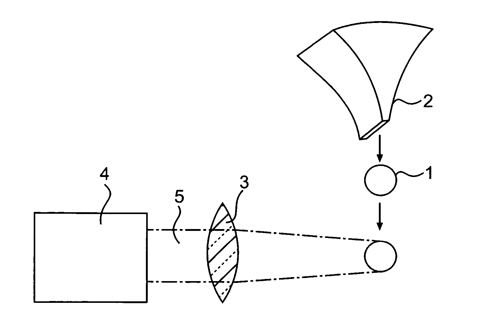
[0072]FIG. 1 is a drawing that shows an example of the target used in the laser plasma EUV light source in the present invention. Target 1 is a disc-shaped target of 1 mm diameter and 100 nm thickness made of Sn. The mechanical strength falls if the thickness is under 100 nm, the target is easy to break and it is difficult to handle the target. The thickness may be increased to impart adequate mechanical strength but holding the thickness under 1000 nm is ideal from a viewpoint of debris removal.
[0073]FIG. 2 is a drawing that shows the method of providing disc-shaped target 1 in the laser plasma EUV light source in the first embodiment of the present invention. Disc-shaped target 1 is sprayed from nozzle 2 that has a slit-shaped aperture and is arranged in the disc direction. Disc-shaped target 1 is conveyed on a gas stream. He gas is used in this example. Nozzle 2 may be vibrated by a piezo apparatus to spray disc-shaped target 1.
[0074] Target 1 that is sprayed from nozzle 2 reach...
second embodiment
[0080]FIG. 4 shows the method of providing disc-shaped targets in a laser plasma EUV light source in the present invention. Tape target 8 in tape form is continuously provided by target drive mechanism 9 in this embodiment. Laser light 5 generated by laser light source 4 is focused by lens 3 and irradiated onto tape target 8. So-called tape target 8 itself has long been known, but tape target 8 having a different structure from the conventional structure is used in this embodiment.
[0081]FIG. 5 (a) shows the structure of such a tape target 8. Polyimide resin is used in tape substrate 10. Each hole 13 is opened in tape substrate 10 and each disc-shaped target 11 is installed via supporting structures 12 in the center of each hole 13.
[0082] Disc-shaped target 11 is made of Sn and is 100 nm thick. The diameter of disc-shaped target 11 is set at 1 mm so as to be virtually equal to the convergent beam diameter of laser light. The diameter of hole 13 is sufficiently larger than the conver...
PUM
 Abstract
Description
Claims
Application Information