Waveform generating circuit and spread spectrum clock generator

a technology of waveform generation circuit and spread spectrum clock, which is applied in the direction of oscillator, pulse generation with predetermined statistical distribution, pulse technique, etc., can solve the problems of inability to achieve ideal spread spectrum, impaired effect of spread spectrum, and technique, however, to pay extra cost in both circuit area and cost, so as to improve the spread spectrum effect without increasing the circuit cost

Active Publication Date: 2007-01-11
ASAHI KASEI ELECTRONICS CO LTD
View PDF5 Cites 18 Cited by
  • Summary
  • Abstract
  • Description
  • Claims
  • Application Information

AI Technical Summary

Benefits of technology

[0028] The present invention can implement a waveform generating circuit for generating a modified triangular wave signal suitable for inputting to a frequency modulation circuit such as a VCO. In addition, according to the present invention, the shape of the triangular wave used for the frequency modulation can be modified by a simple method, which makes it possible to implement the spread spectrum clock generator capable of improving the spread spectrum effect without increasing the circuit cost so much.

Problems solved by technology

However, when the frequency characteristic applied for the input to the modulation circuit or the oscillator is insufficient for achieving the frequency modulation by the triangular wave as described above, there arises a problem in that the vertices of the triangular wave round, and ideal spread spectrum is not achieved.
When the spread spectrum is brought about by the triangular wave with such a shape, a spectrum is observed which has higher level portions at both ends of the spread spectrum than in other regions, which presents a problem in that the effect of the spread spectrum is impaired.
As a result, a problem arises in that the spectrum is observed which has the higher level portions than in the other regions (see FIG. 7A).
The technique, however, must pay extra cost in both a circuit area and cost (see Electromagnetic Compatibility EMC, May, pp.

Method used


Image

  • Waveform generating circuit and spread spectrum clock generator
  • Waveform generating circuit and spread spectrum clock generator
  • Waveform generating circuit and spread spectrum clock generator

Examples


Embodiment Construction

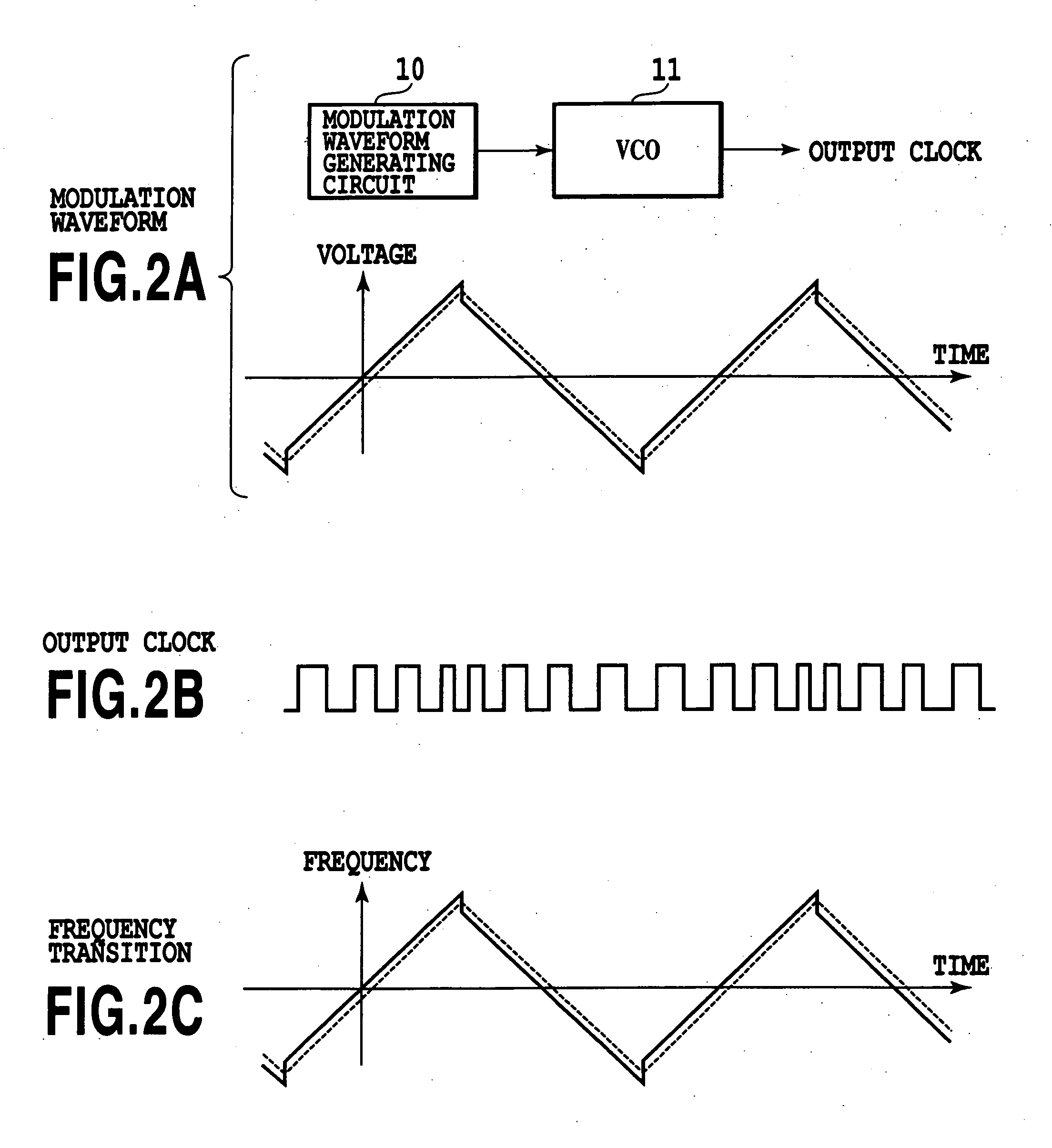
[0042]FIGS. 2A-2C show a spread spectrum clock generator of an embodiment in accordance with the present invention, and signal waveforms of various portions. In these figures, the reference numeral 10 designates a modulation waveform generating circuit whose output signal has a modulation waveform as illustrated by solid lines in FIG. 2A. The modulation waveform is input to a VCO (voltage-controlled oscillator) 11. Thus, the oscillation frequency of the VCO 11 is modulated in response to the modulation waveform, providing the output clock with frequency variations as illustrated in FIG. 2B. The frequency transition of the output clock has temporal variations as indicated by solid lines of FIG. 2C.

[0043]FIG. 3 shows an example of a method of generating the modulation waveform represented by solid lines in FIG. 2A. FIG. 3(a) shows a pure triangular wave, and FIG. 3(b) shows a rectangular wave for an offset, which has transition points at the same timing as the vertices of the triangu...


PUM


Abstract

A spread spectrum clock generator is provided which improves the spread spectrum effect with little increasing the circuit cost by modifying the shape of a triangular wave used for frequency modulation by as simple method. The output signal of the modulation waveform generating circuit has such a modulation waveform as indicated by solid lines in FIG. 2A. The modulation waveform is input to a VCO (voltage-controlled oscillator). In response to the modulation waveform, the oscillation frequency of the VCO is modulated, and the output clock that varies its frequency as illustrated in FIG. 2B is obtained. The frequency transition of the output clock involves such temporal variations as indicated by solid lines in FIG. 2C.

Description

[0001] This application claims priority from Japanese Patent Application No. 2004-363094 filed Dec. 15, 2004, which is incorporated hereinto by reference. BACKGROUND OF THE INVENTION [0002] 1. Field of the Invention [0003] The present invention relates to a waveform generating circuit for making certain modifications to a triangular wave signal, and to a spread spectrum clock generator using the waveform generating circuit. [0004] The spread spectrum clock generator refers to a clock generator for reducing electromagnetic radiation by varying the clock frequency by the so-called spread spectrum clock technique. [0005] 2. Description of the Related Art [0006] In the field of the digital circuit, it is known to vary the clock frequency slightly to reduce the electromagnetic radiation caused by the clock. [0007] To obtain the frequency modulated clock, it is generally performed to input a triangular wave to a VCO (voltage-controlled oscillator). [0008]FIG. 1 shows an example of a trian...

Claims


Application Information

Patent Timeline
Patent Type & Authority Applications(United States)
IPC IPC(8): H03B21/00
CPCH03K3/84H04B2215/067H04B15/02H03K7/06
Inventor NAGASHIMA, TAMOTSUTOMIOKA, KOJI
Owner ASAHI KASEI ELECTRONICS CO LTD
Why Eureka
Try Eureka