
Apparatus and method for shading correction and recording medium therefore

Inactive Publication Date: 2007-01-11
FUJITSU LTD
View PDF3 Cites 7 Cited by
  • Summary
  • Abstract
  • Description
  • Claims
  • Application Information

AI Technical Summary

Benefits of technology

[0019] The present invention has been developed to solve the above-mentioned problems, and aims at providing a shading correction apparatus, method, and program capable of performing high-speed and high-quality correction.
[0021] According to the present invention, after the background image data generation unit smoothes the gray scale of the image data captured by the capture unit, it shifts the boundary area between the object and the background outside the contour of the object captured in the image data, thereby possibly preventing the excess correction by the shading correction due to the gray-scale boundary area.
[0022] As described above, according to the present invention, a shading correction apparatus, method, and program capable of performing high-speed and high-quality correction can be provided.

Problems solved by technology

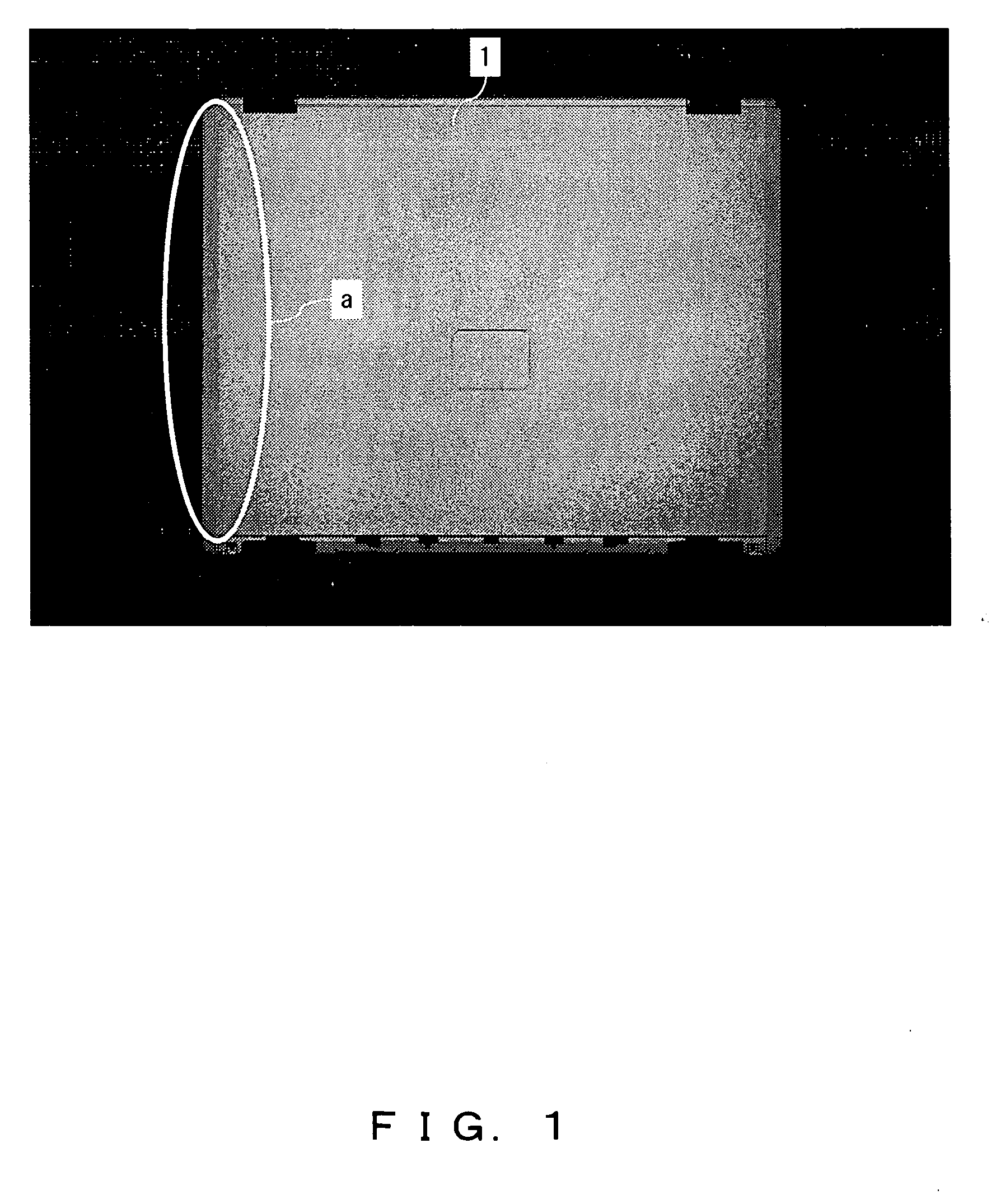
However, in many cases an image captured by a camera, etc. is accompanied by uneven luminance from the center to circumference of the image depending on the uneven illumination and the characteristic of a lens.
Accordingly, when the image data is analyzed, erroneous detection or determination frequently occurs.
However, since there are variations in surface of a product manufactured on a production line, there are also variations in uneven luminance, and desired shading correction can be hardly performed.
However, the larger the original image treated in the digital filter process requiring more arithmetic operations, the longer the time required to generate a background image.
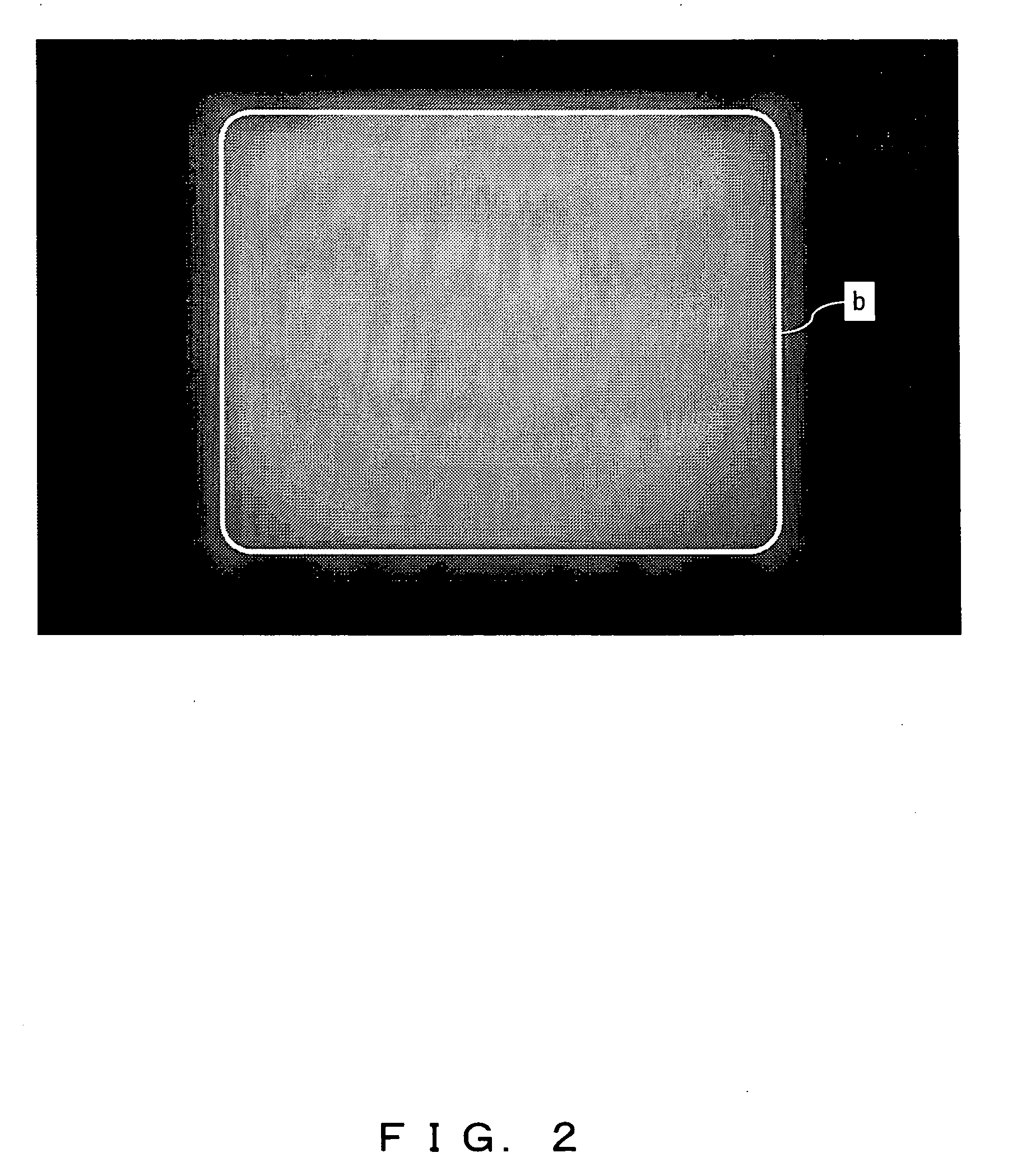
Accordingly, when shading correction is performed on the original image data using the background image data, the luminance inside the boundary line b is excessively corrected.
Since the luminance value at the outside of the boundary line b is higher than the practical value, the luminance is excessively corrected when the shading correction is performed.

Method used


Image

  • Apparatus and method for shading correction and recording medium therefore
  • Apparatus and method for shading correction and recording medium therefore
  • Apparatus and method for shading correction and recording medium therefore

Examples


Embodiment Construction

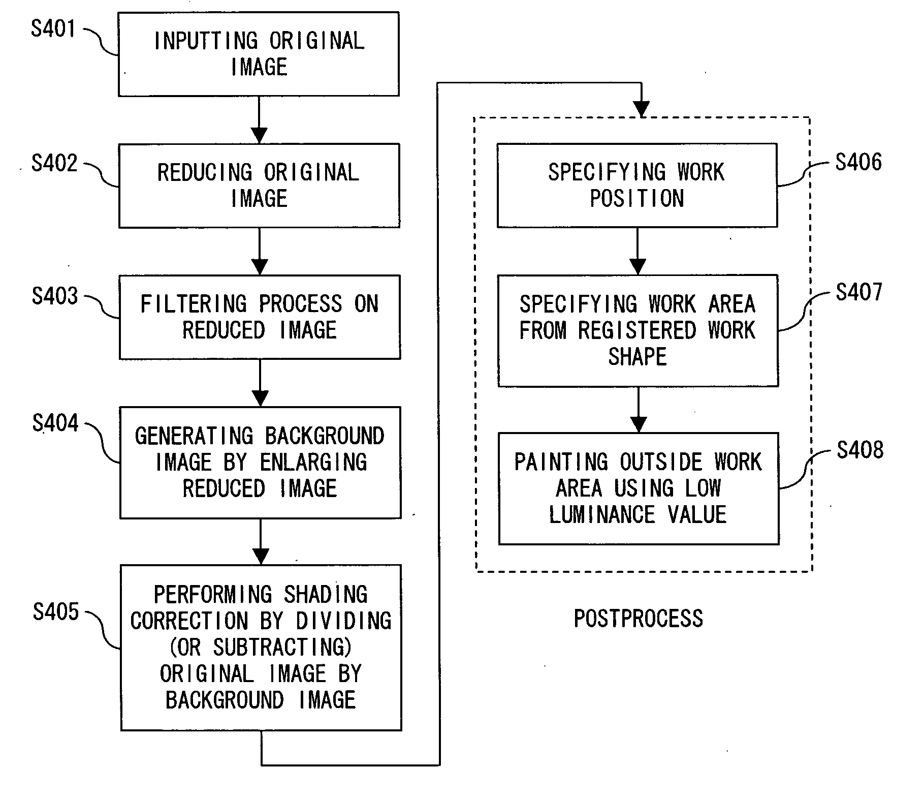
[0038] The embodiments of the present invention are explained below by referring to FIGS. 4 through 15.

[0039]FIG. 4 shows the principle of the shading correction apparatus according to the present invention.

[0040] The shading correction apparatus shown in FIG. 4 comprises a capture unit 2 for capturing a work 1 as an object to be captured, a background image data generation unit 3 for generating background image data from the image data generated by the capture unit 2 (hereinafter referred to as “original image data”), and a correcting process unit 4 for correcting the uneven luminance of the original image data using the background image data.

[0041] The work 1 is, for example, a product manufactured on a production line in a factory, etc., and the presence / absence of a defect can be determined by analyzing the image data obtained by capturing the product.

[0042] The capture unit 2 captures the work 1, and can be, for example, a CCD camera for generating original image data of th...


PUM


Abstract

A shading correction apparatus, method, and program capable of realizing high-speed and high-quality correction include: a work as an object to be captured; a capture unit for capturing the work; a background image data generation unit for generating background image data from original image data generated by the capture unit; and a correcting process unit correcting uneven luminance of the original image data using the background image data.

Description

BACKGROUND OF THE INVENTION [0001] 1. Field of the Invention [0002] The present invention relates to a shading correction apparatus and method capable of correcting the uneven luminance of an image obtained by capturing an object, and a program for them. [0003] 2. Description of the Related Art [0004] To manage the quality of a product, etc. manufactured on a production line in a factory, etc., for example, checking the presence / absence of a defect of a product by capturing the appearance of a product using a camera, etc. and analyzing image data is commonly performed in a producing step. [0005] However, in many cases an image captured by a camera, etc. is accompanied by uneven luminance from the center to circumference of the image depending on the uneven illumination and the characteristic of a lens. Accordingly, when the image data is analyzed, erroneous detection or determination frequently occurs. Therefore, the uneven luminance caused on image data is normally corrected (herei...

Claims


Application Information

Patent Timeline
IPC IPC(8): G06K9/40
CPCG06T5/50G06T5/20G06T5/008G06T7/0004G06T5/94
Inventor WAKABAYASHI, AKIHIRO
Owner FUJITSU LTD
Learn More