Method and device for correcting guiding errors in a coordinate measuring machine

Inactive Publication Date: 2005-05-12
CARL ZEISS IND MESSTECHN GMBH
View PDF7 Cites 27 Cited by
  • Summary
  • Abstract
  • Description
  • Claims
  • Application Information

AI Technical Summary

Benefits of technology

[0010] Against this background, it is the object of the invention to provide a high-quality correction even for measuring errors which are caused by elastic deformations of the measuring appar

Problems solved by technology

Under some circumstances, the absolute value also included an unknown offset resulting from the measuring operation, and it was additionally affected by influences of errors of the second spatial direction.

Method used


Image

  • Method and device for correcting guiding errors in a coordinate measuring machine
  • Method and device for correcting guiding errors in a coordinate measuring machine
  • Method and device for correcting guiding errors in a coordinate measuring machine

Examples


Embodiment Construction

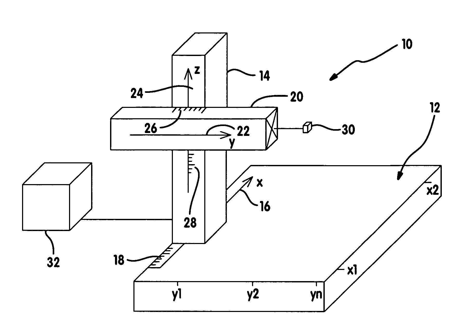
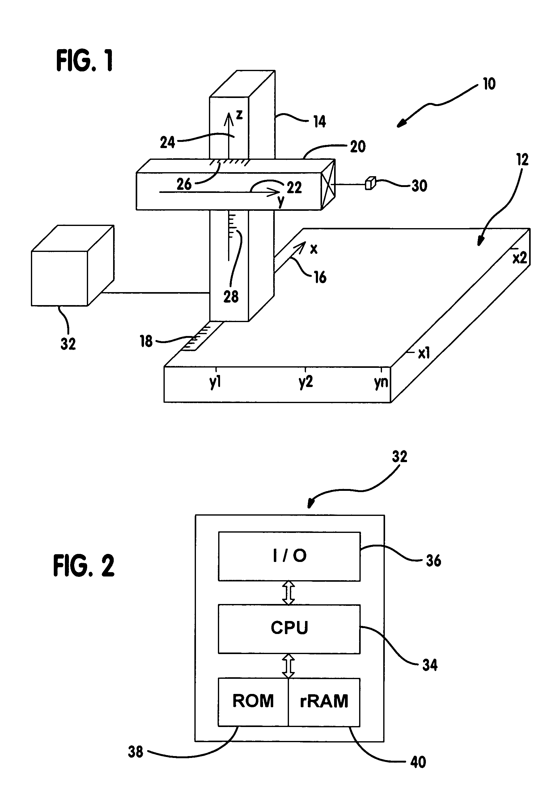
[0068] An overall view of a horizontal arm measuring machine as an example of a coordinate measuring machine is denoted by numeral 10 in FIG. 1. The horizontal arm measuring machine 10 has a reference plane 12 on which a column 14 can move along an X direction 16. The reference plane 12 is, for example, a measuring table or as flat as possible a surface in space. The position of the column 14 can be read off an X scale 18. The column 14 supports horizontal arm 20 which can move in the Y direction 22 and Z direction 24. The Y position of the horizontal arm 20 and its Z position can be read off on a Y scale 26 and a Z scale 28, respectively. The horizontal arm 20 supports a measuring head 30 with the aid of which workpiece positions or components can be approached. The X, Y and Z positions reached by the measuring head 30 when touching the components can be read off on the said scales, and / or acquired by suitable sensor systems and transmitted to an evaluation apparatus 32 for further...


PUM


Abstract

A method for correcting errors in a coordinate measuring machine having a measuring head which is adapted to move in at least two different spatial directions. Measuring scales and measuring lines are assigned to each spatial direction. The measuring lines of different spatial directions intersect, and correction values are determined along the measuring lines at predetermined values of the scales in order to correct for elastic and / or geometric errors of the scales and / or of the guiding mechanism for moving the measuring head. According to one aspect of the invention, the correction values determined along a measuring line of a first spatial direction are modified such that the modified correction value of this measuring line assumes a predetermined value at the point of intersection with a first measuring line of a second spatial direction.

Description

REFERENCE TO RELATED APPLICATIONS [0001] This application is a continuation of international patent application PCT / EP03 / 00217, filed on Jan. 13, 2003 and published as WO 03 / 081168 in German language, which claims priority under the Paris convention from German patent application DE 102 14 490.7 filed on Mar. 26, 2002. BACKGROUND OF THE INVENTION [0002] The invention relates to a method and a device for correcting errors in a coordinate measuring machine having a movable measuring head and elements for guiding the measuring head in at least two different spatial directions. [0003] According to DE 33 34 460 A1, a position of a measuring head of a coordinate measuring machine is determined interferometrically. The interferometrical value is compared by means of an evaluation device with values are supplied by a scaling, such as an optically and / or electrically scannable sequence of mechanical marks. Deviations between values supplied from the scales and the values provided by the inte...

Claims


Application Information

Patent Timeline
IPC IPC(8): G01B11/00G01B11/30G01B21/00G01B21/04
CPCG01B11/005G01B21/045G01B21/04G01B11/306
Inventor GRUPP, GUENTERFUCHS, ANDREASJENISCH, WALTERBERNHARDT, RALFSCHMID, HARALDSTAADEN, ULRICH
Owner CARL ZEISS IND MESSTECHN GMBH
Why Eureka
Try Eureka