

Target assembly for holding clay targets
a target and assembly technology, applied in the direction of movable targets, weapons, target ranges, etc., can solve the problems of inability to discern whether the second is the case, all conventional products fail to provide sufficient visual confirmation, and are often expensiv
- Summary
- Abstract
- Description
- Claims
- Application Information
AI Technical Summary
Benefits of technology
Problems solved by technology
Method used
Image

Examples
Embodiment Construction
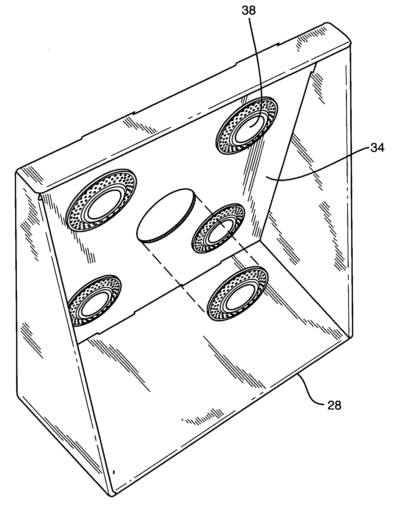
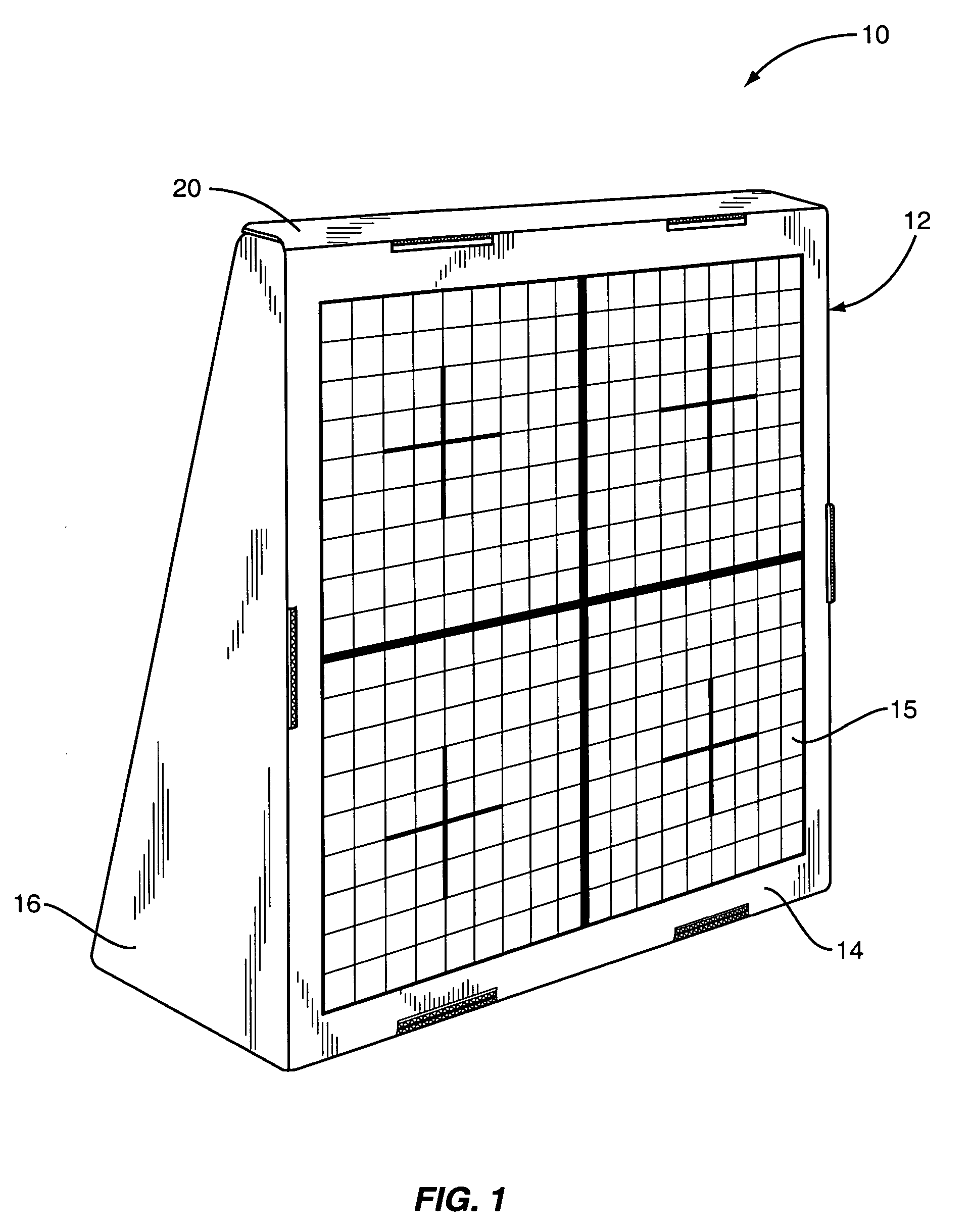
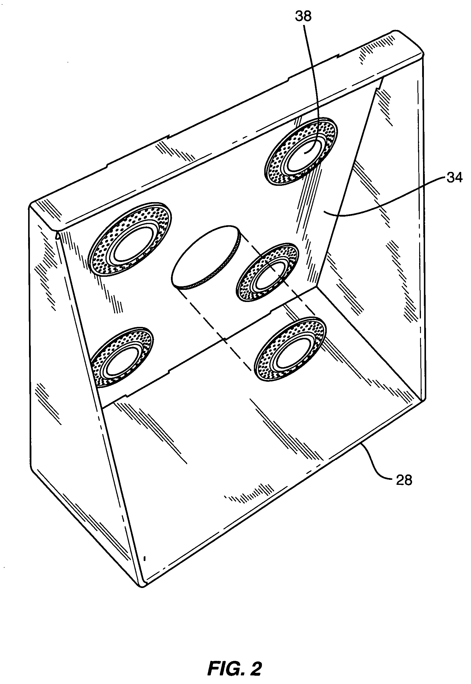
[0014] With further reference to the drawings, one embodiment of the target assembly of the present invention is shown therein and indicated generally by the number 10. As will be appreciated from other portions of the disclosure, the target assembly 10 is adapted to be used to hold clay targets for target practice or sighting. The embodiment addressed herein is collapsible, foldable, and self-supporting.
[0015] Target assembly 10 may be constructed of various sheet materials, but it is contemplated that in one embodiment it would be constructed of cardboard. Plastic materials could also be used. The embodiment herein illustrated is formed from a single piece of cardboard by stamping. Other fabrication methods could be used. The thickness or gauge of the material utilized for the target assembly 10 can vary to suit various types of applications.
[0016] Turning to FIGS. 1 and 2, the target assembly 10 is pictured. FIG. 1 shows a perspective of the erected target assembly 10 from the ...
PUM
 Abstract
Description
Claims
Application Information