Combination razor and shaving cream dispenser

Inactive Publication Date: 2007-01-25
TOMASSETTI LOUIS
View PDF19 Cites 16 Cited by
  • Summary
  • Abstract
  • Description
  • Claims
  • Application Information

AI Technical Summary

Problems solved by technology

This will cause the valve to o

Method used


Image

  • Combination razor and shaving cream dispenser
  • Combination razor and shaving cream dispenser
  • Combination razor and shaving cream dispenser

Examples


Embodiment Construction

[0017] All of the FIGS. show a single embodiment.

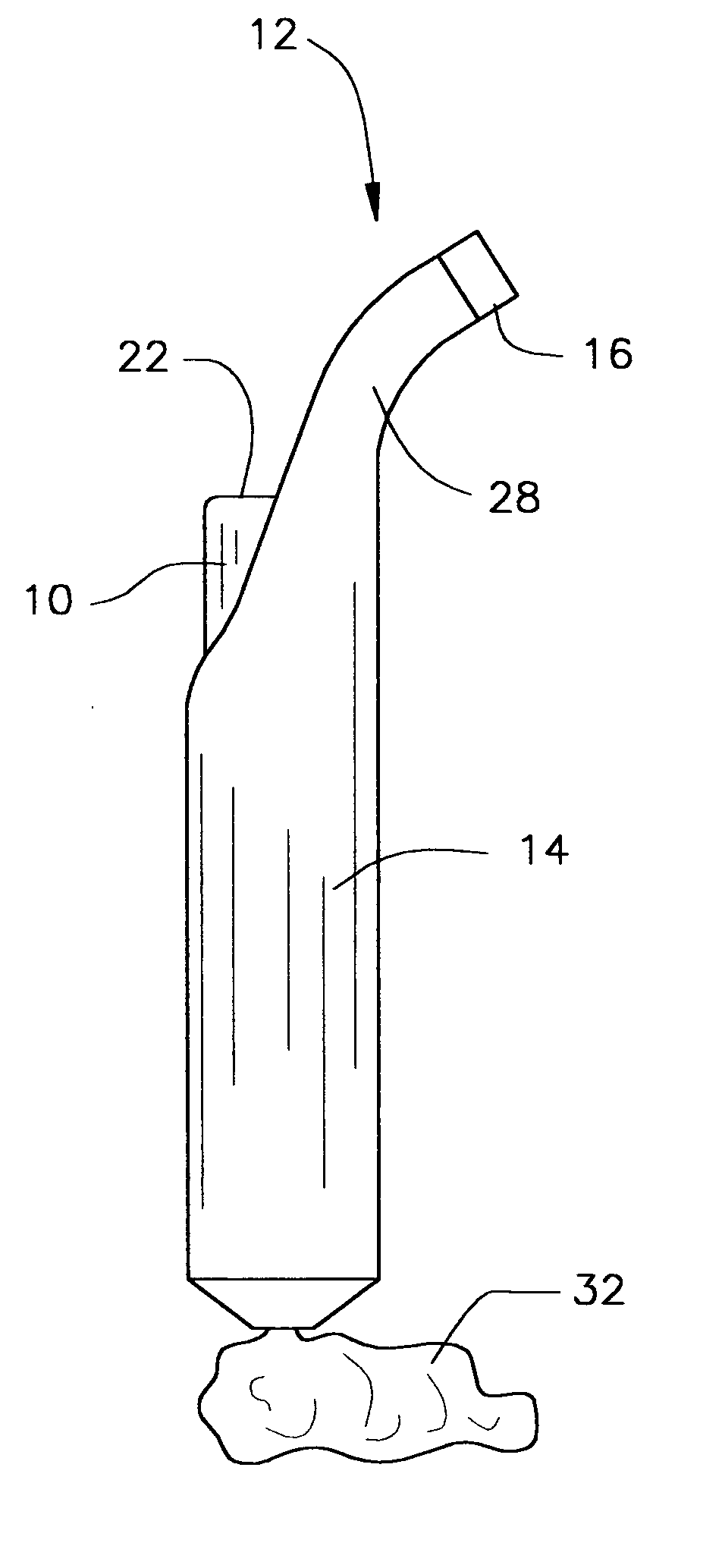
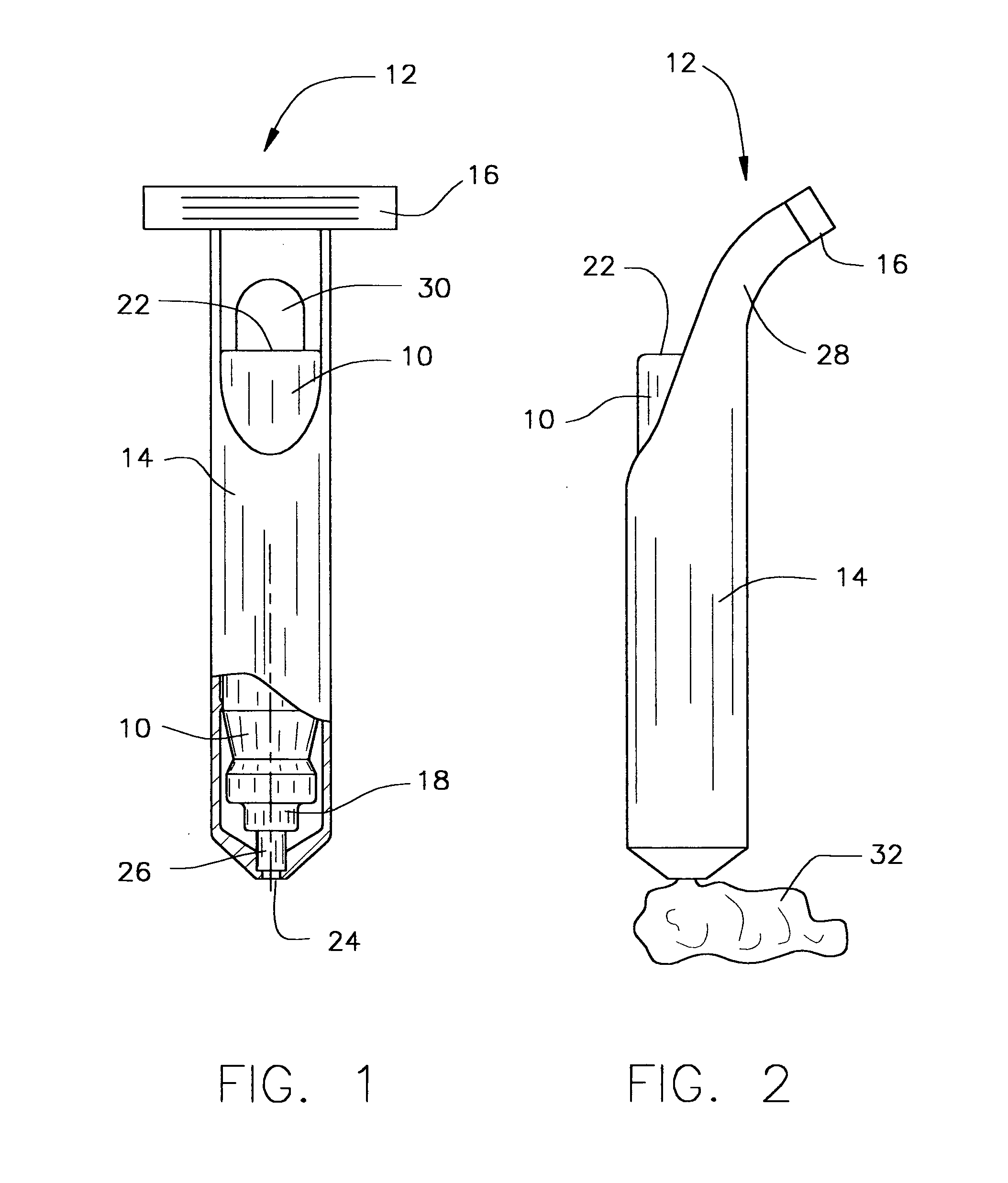
[0018] A pressurized shaving cream dispenser 10 is mounted for sliding movement within the handle 14 of a razor 12. The dispenser 10 is mounted in an upside down fashion so that the shaving end 16 is at one end of the combination and the dispensing valve 18 of the pressurized dispensing container is at the other end of the combination.

[0019] The dispending container 10 is mounted for axial movement within the handle 14 of the razor 12. The back of the neck 28 near the upper portion of the razor handle 14 is cut away to permit manual access to the base 22 of the dispensing container 10.

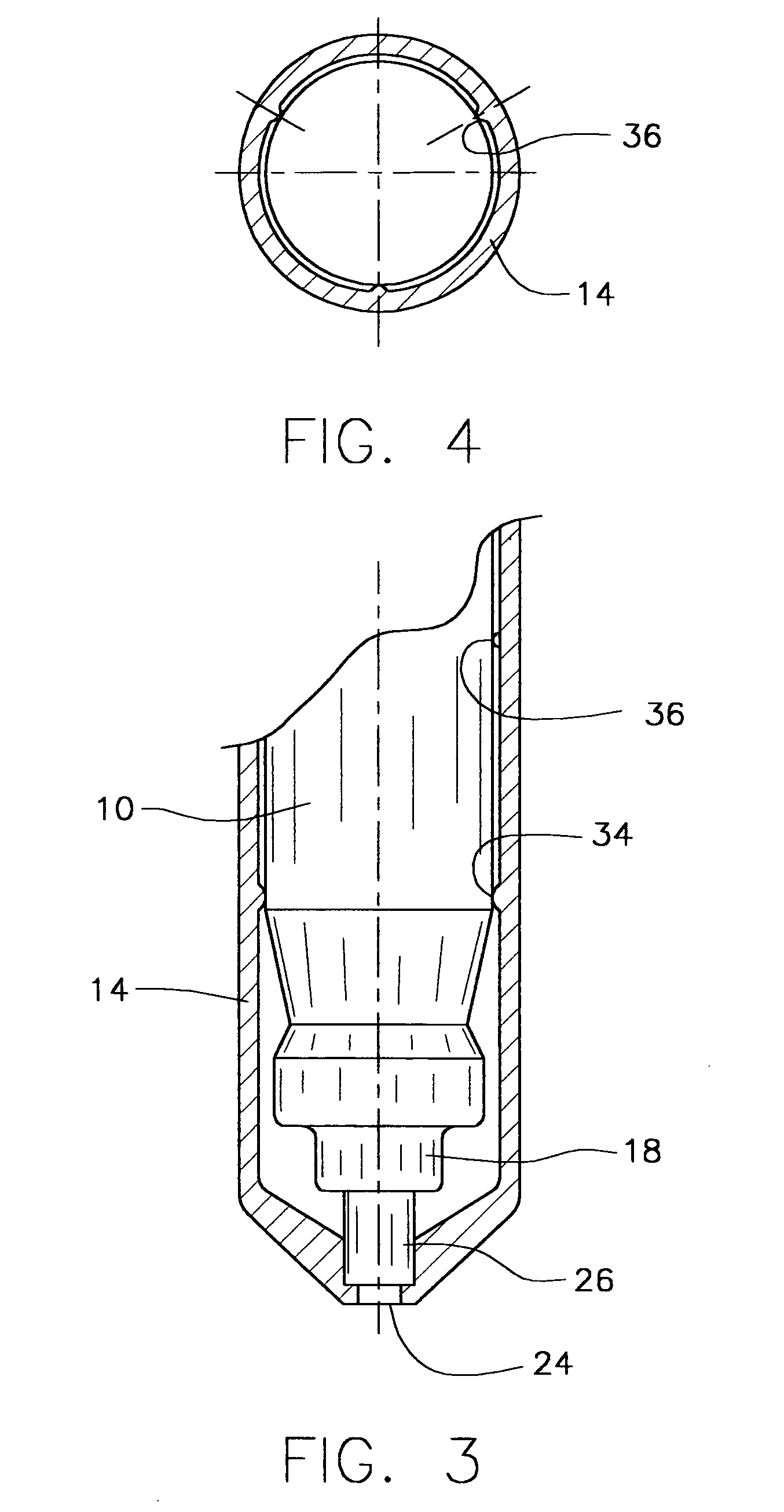
[0020] A small opening 24 at the lower end of the handle 14 is sized to engage the wall of the valve stem 26 so that there is communication between the bore 46 of the valve stem 26 and the dispensing opening 24. When a user pushes down on the base 22 of the pressurized dispenser 10, the valve stem 26, which is resting on the edge of the opening 24, is...


PUM


Abstract

A razor has a hollow handle in which a pressurized dispensing container is mounted to dispense shaving cream. The valve end of the container is positioned at the lower end of the handle so that gravity feed is employed to provide shaving cream at the valve. The dispensing valve is in communication with a dispensing opening at the end of the handle. The valve is spring loaded into a normally closed state. An opening at the upper end of the handle lets the user apply a finger to the base of the dispenser to push the dispenser down. When pushed down, the valve stem abuts against a rim at the dispensing opening of the razor thereby moving the valve into its open state. Shaving cream is thus dispensed through the bore of the valve stem and the dispensing opening at the end of the handle.

Description

BACKGROUND OF THE INVENTION [0001] This invention relates to a pressurized shaving cream dispenser and a razor combined to provide a minimum cost, easy to handle product. [0002] It is known to combine a razor with a shaving cream dispenser as shown in U.S. Pat. No. 5,070,611 dated Dec. 10, 1991, U.S. Pat. No. 4,791,723 dated Dec. 20, 1988 and U.S. Pat. No. 4,443,483 dated Feb. 28, 1984. For the convenience of the user, it is desirable to provide such a combination that facilitates single handed use when dispensing shaving cream. [0003] Thus, it is one object of this invention to provide a device in which shaving cream can be dispensed using one hand. [0004] It is also desirable to provide such a device in as simple a structure as possible, employing few parts, so as to provide a minimum cost combination device that will facilitate widespread use. [0005] Accordingly, it is an object of this invention to provide such a combination with as few parts as possible so as to reduce the cost...

Claims


Application Information

Patent Timeline
IPC IPC(8): B26B19/44
CPCB26B21/446
Inventor SCHEINDEL, CHRISTIAN T.
Owner TOMASSETTI LOUIS
Why Eureka
Try Eureka