Fastener with prongs

a technology of prongs and fasteners, applied in the field of fasteners, can solve the problems of difficult to ensure that there is sufficient penetration into the sides of the hole, the difficulty of fasteners, and the difficulty of riveting fasteners, and achieve the effect of preventing shingling

Active Publication Date: 2007-01-25
FALCON FASTENERS REGD
View PDF18 Cites 7 Cited by
  • Summary
  • Abstract
  • Description
  • Claims
  • Application Information

AI Technical Summary

Benefits of technology

[0012] According to some embodiments of the present invention, when the fastener is inserted into a piece of material the prong embeds itself within a surface of the piece of material, thereby precluding rotation of the fastener when a threaded fastener is threaded into the threaded opening in the shaft thereof. In addition, according to some embodiments of the present invention, the thickness of the flange is sufficient such that the straight sides of two fasteners abut while in a curved portion of a guide track, thus preventing shingling.

Problems solved by technology

However, riveting fasteners, which would be desirable to prevent rotation of the fasteners, is difficult in several situations, including the following:
When using conventional riveting methods, it is difficult to ensure that there is sufficient penetration into the sides of the hole to prevent rotation when the hole is opening up.
It is very difficult to ensure consistently good riveting into different depth holes with a single set-up.

Method used


Image

  • Fastener with prongs
  • Fastener with prongs
  • Fastener with prongs

Examples


Embodiment Construction

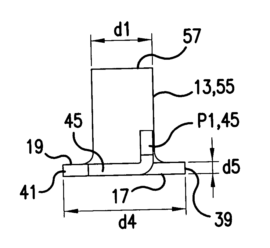
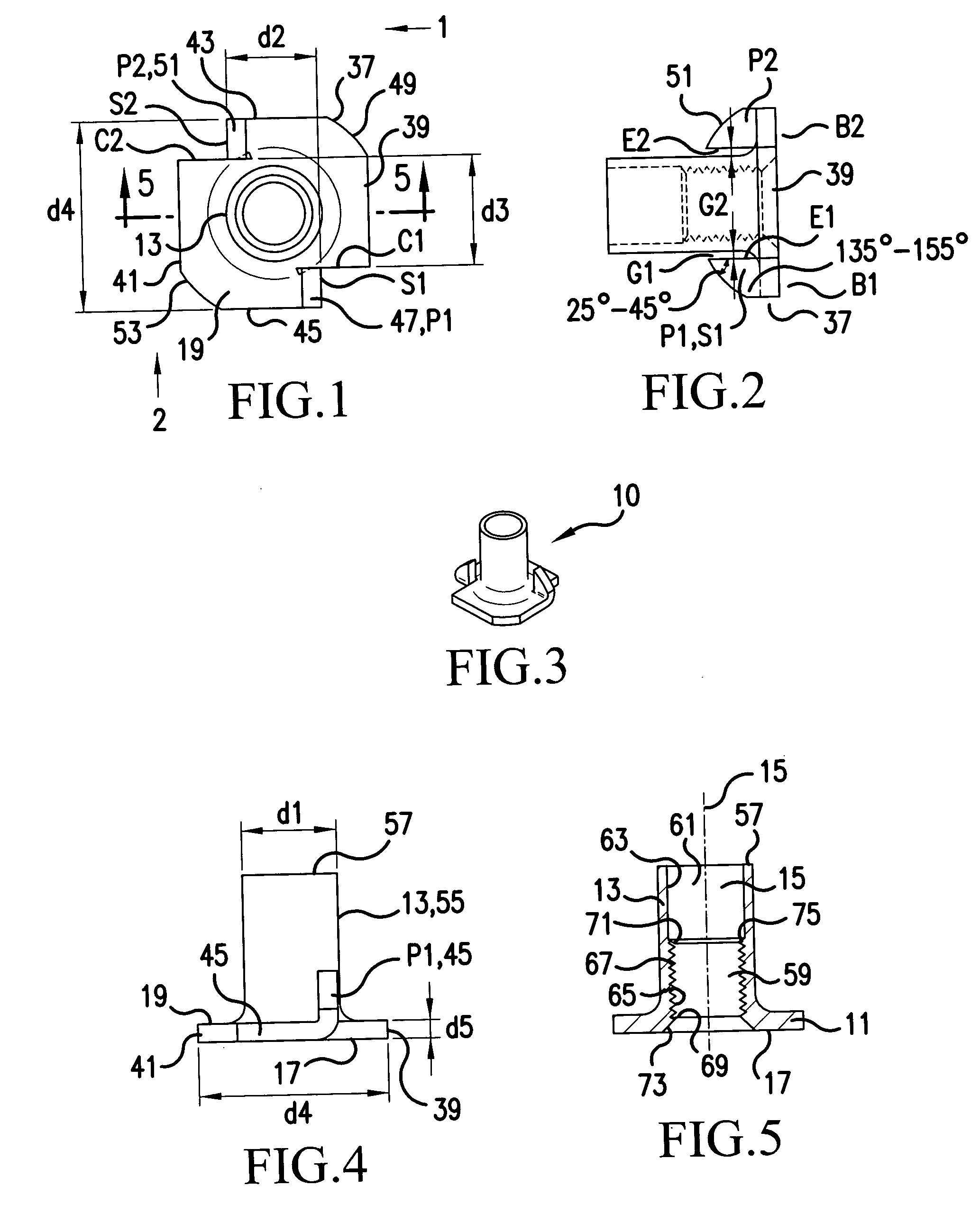
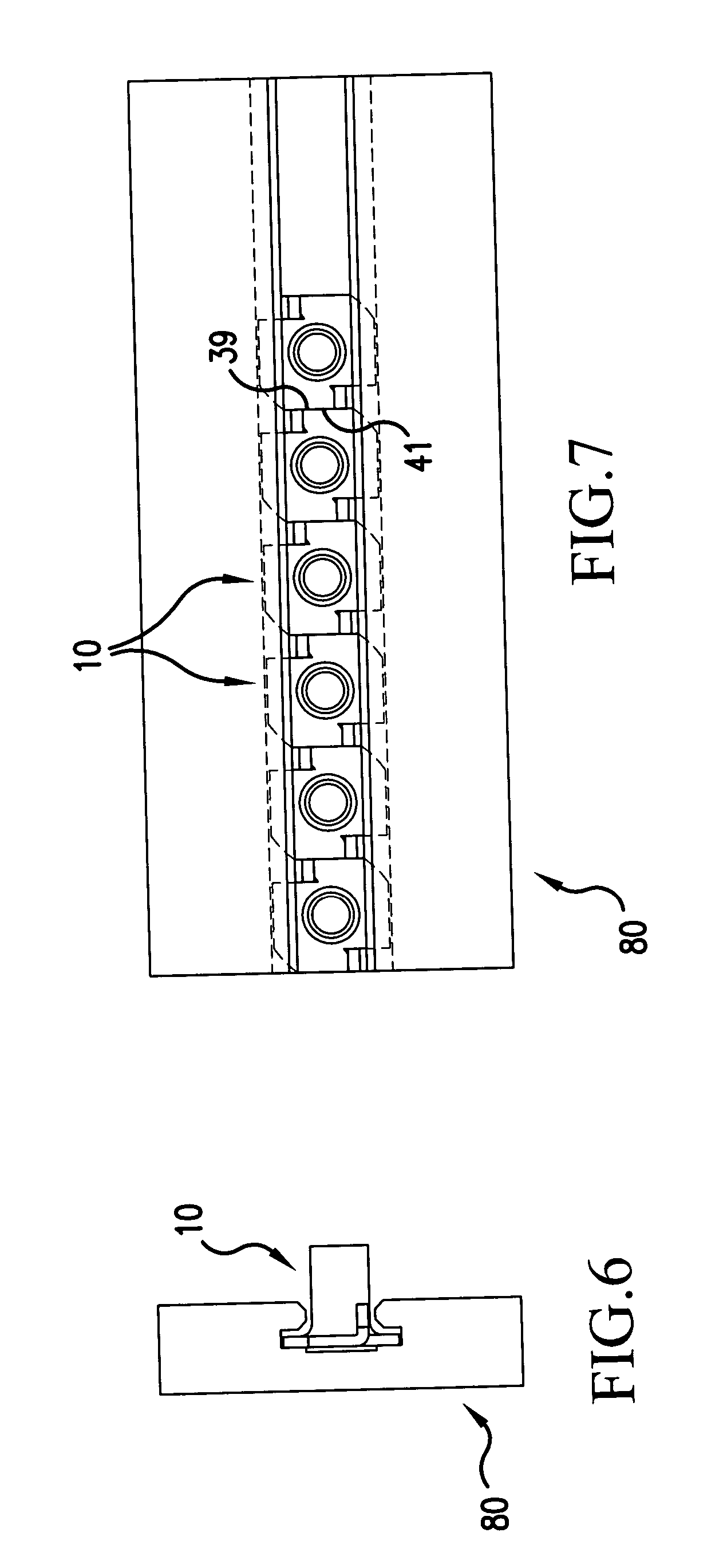
[0029] With reference to FIGS. 1-5, the inventive fastener is generally designated by the reference numeral 10 and is seen to include a flange 11 and a shaft 13 extending therefrom. The shaft 13 has an axis of elongation 15 (FIG. 4) that is perpendicular to the bottom surface 17 of the flange 11.

[0030] The flange 11 also has a top surface 19 (FIG. 1) extending upwardly therefrom.

[0031] As best seen in FIGS. 1 and 2, the flange 11 has a periphery 37 including one pair of flat side walls 39 and 41 opposed from one another about the periphery of the flange 11, a second pair of opposed flat side walls 43 and 45, and arcuate side walls 47, 49, 51 and 53. In one embodiment, each of the four flat walls and the four arcuate walls is generally perpendicular to the top surface 19 of the flange 11.

[0032] Two prongs P1, P2 may be formed by making cuts C1, C2 in opposing straight sides 39, 41 adjacent to the diagonally opposing arcuate corners 47, 51, and then bending at points B1, B2 periphe...


PUM


Abstract

A fastener with a flange having two pairs of parallel sides and arcuate corners. Extending upwardly from the top surface of the flange is an elongated shaft having one region adjacent the flange having relatively thicker threaded walls and another distal from the flange having thinner unthreaded walls. Two prongs are formed by making cuts in opposing straight sides adjacent to the diagonally opposing arcuate corners, and then bending peripheral portions of the flange including the arcuate corners adjacent to the cuts in a direction upwardly by substantially 90°. The depth of the cuts is such that when bends are made, the perpendicular distance between front surfaces of the two prongs is less than an outer diameter of the shaft. When the fastener is inserted in a piece of material, the prongs dig into the surface of the material to prevent the fastener from rotating when a threaded fastener is screwed into the shaft.

Description

BACKGROUND OF THE INVENTION [0001] 1. Field of the Invention [0002] The present invention relates to a fastener. When the fastener is inserted in a piece of material, at least one prong digs into the surface of the material to prevent the fastener from rotating when a threaded fastener is screwed into the fastener. [0003] 2. Description of Background Art [0004] Fasteners including a flange with a shaft extending therefrom are well known. It is also well known to provide the shaft with an end remote from the flange having a reduced wall thickness to facilitate riveting that end over the surface of a piece of material through which the shaft has been inserted to hold the fastener against axial movement once riveted. Rivets may also prevent rotation of the fastener, particularly rivets which have alternating flaired and non-flaired portions. [0005] However, riveting fasteners, which would be desirable to prevent rotation of the fasteners, is difficult in several situations, including t...

Claims


Application Information

Patent Timeline
Patent Type & Authority Applications(United States)
IPC IPC(8): F16B15/00
CPCF16B37/065F16B27/00
Inventor LEISTNER, MARTIN
Owner FALCON FASTENERS REGD
Why Eureka
Try Eureka