Metering Fuel Pump

a fuel pump and metering technology, applied in the direction of combustion types, lighting and heating apparatus, instruments, etc., can solve the problems of adding to the parts count and complexity of these engines, and achieve the effect of eliminating the throttle pla

Inactive Publication Date: 2007-02-08
NEW POWER CONCEPTS
View PDF5 Cites 18 Cited by
  • Summary
  • Abstract
  • Description
  • Claims
  • Application Information

AI Technical Summary

Benefits of technology

[0005] The system may be used advantageously to both control the fuel flow and increase the pressure of the gas supplied to the combustion chamber. The system advantageously eliminates the throttle plate or valve or other restrictive device that is used to control the flow of fuel to the chamber in prior art systems.

Problems solved by technology

This restrictive device adds to the parts count and complexity for these engines.

Method used


Image

  • Metering Fuel Pump
  • Metering Fuel Pump
  • Metering Fuel Pump

Examples


Embodiment Construction

[0015] The fuel flow to a pressurized combustion chamber may be metered by varying the operating parameters of a fuel pump. Desired performance may be achieved without the throttle plates or valves or other restrictive devices that are normally used to meter the fuel flow to the combustion chamber.

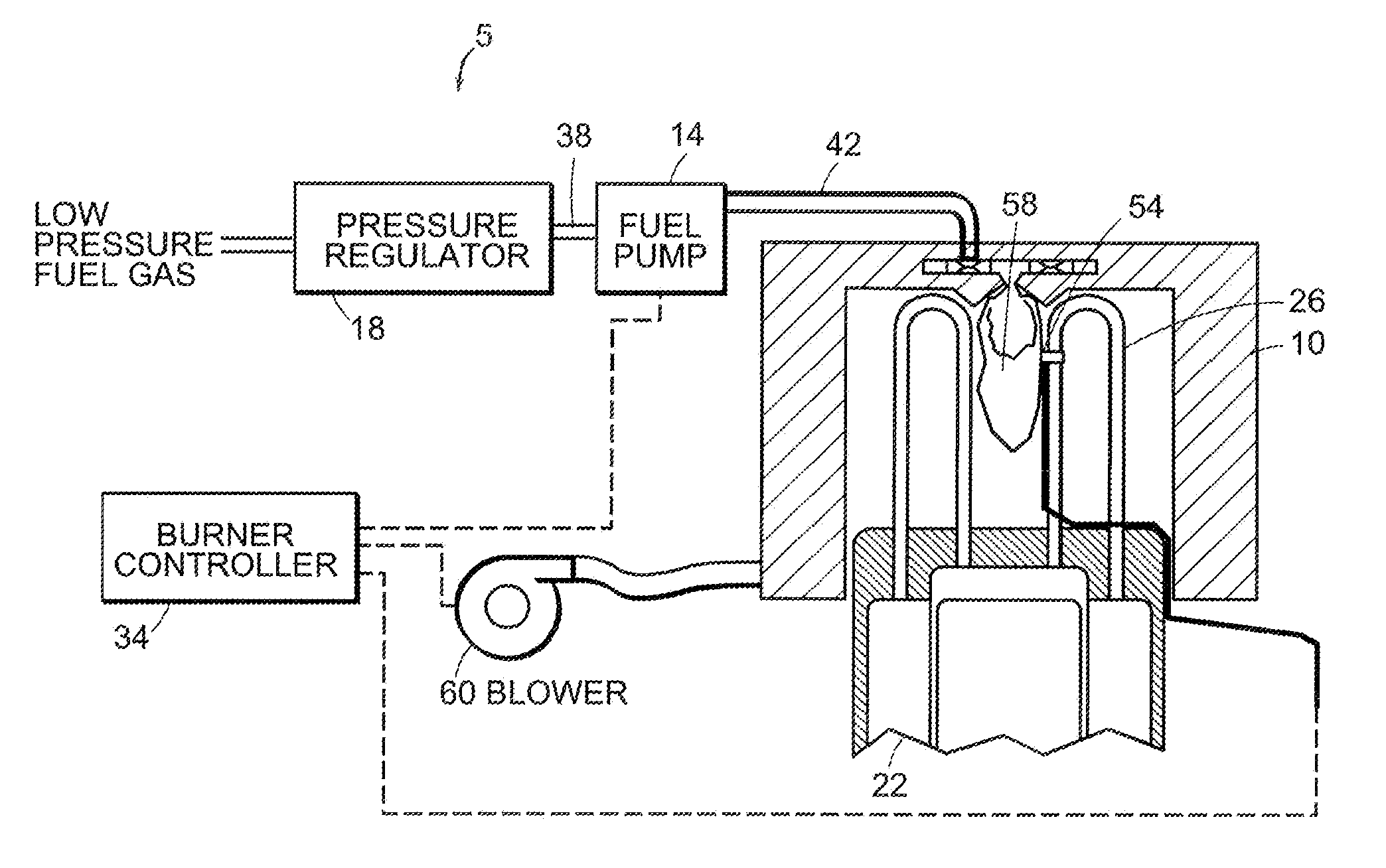
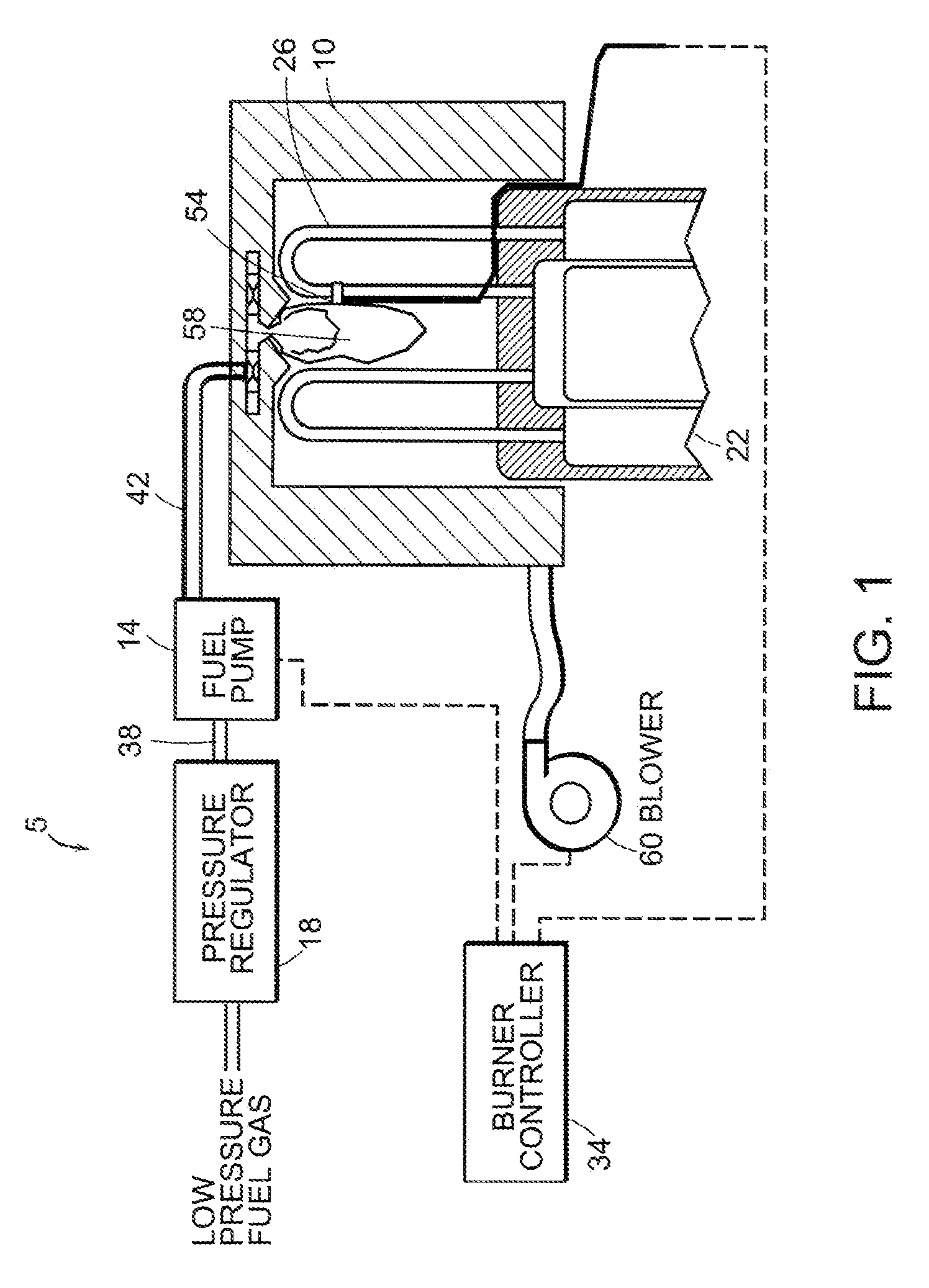
[0016]FIG. 1 shows a metering pump system providing gaseous fuel to a pressurized combustion chamber 58 of an engine 22 according to an embodiment of the invention. A gas train, labeled generally as 5, includes a fuel pump 14, interconnecting lines 38, 42 and may include a pressure regulator 18. The fuel pump 14 raises the fuel pressure in line 38 to a higher pressure in line 42. The gas train delivers fuel from the gas supply to the burner 10, where it is mixed with air and burned in a combustion chamber 58. The fuel pump is controlled by a controller 34 that modulates the fuel flow rate by varying one or more parameters of an electrical signal sent to the fuel pump 14. The controller ma...


PUM


Abstract

A device and method for controlling the flow of a gaseous fuel from a fuel supply to a pressurized combustion chamber. A fuel pump is included in the gas train from supply to chamber. The fuel pump increases the pressure of the gas to allow efficient injection into the chamber. The pump is modulated to control the fuel flow. Both alternating current and pulse-width-modulated direct current signals may be used to control the flow. The pump may be a piston pump or a diaphragm pump. Feedback may be provided from sensors that determine operating parameters of the engine and such sensor signals may be used by the controller to maintain a parameter, such as temperature, at a specified value. An acoustic filter can be included in the gas train to significantly reduce gas flow pulsations generated by the pump. This filter improves the uniformity of the combustion process.

Description

[0001] The present application is a continuation of U.S. patent application Ser. No. 10 / 643,147, atty. docket 2229 / 134 filed on Aug. 08, 2002 which is a continuation-in-part of U.S. patent application Ser. No. 09 / 853,239, filed May 11, 2001, atty. docket 2229 / 119, which is a continuation-in-part of U.S. patent application Ser. No. 09 / 517,686, atty. docket 2229 / 112, filed Mar. 2, 2000. The present application is also a continuation-in-part of U.S. patent application Ser. No. 10 / 361,354, filed Feb. 10, 2003, atty. docket 2229 / 144, which is a divisional application of U.S. patent application Ser. No. 09 / 883,077, filed Jun. 15, 2001, atty. docket no. 2229 / 118. All of the preceding applications are incorporated herein by reference in their entirety.TECHNICAL FIELD [0002] The present invention relates to metering fuel pumps for pressurized combustion chambers. BACKGROUND [0003] Engine burner, such as those used in Stirling engines, have one or more heat exchangers that produce significant...

Claims


Application Information

Patent Timeline
Patent Type & Authority Applications(United States)
IPC IPC(8): F02G1/04F02G1/043F02G1/047F02G1/055F23D14/60F23N1/00F23N1/02F23N3/08F23N5/00G05D7/06
CPCF02B77/085F02D19/027F02G1/047F02G1/055F02G2244/00F02G2254/10F02G2255/00F23D14/60F23K5/007F23K2401/201F23K2900/05003F23N1/002F23N1/022F23N3/082F23N5/006F23N2021/08F23N2025/14F23N2027/02F23N2027/04F23N2033/08G05D7/0676Y02T10/32F02M21/0212F02M21/0245F02D19/023F02G1/043F23N2221/08F23N2225/14F23N2227/02F23N2227/04F23N2233/08F23K2400/201Y02T10/30
Inventor JENSEN, ERIC R.LANGENFELD, CHRISTOPHER C.NEWELL, SCOTT W.NORRIS, MICHAELRENK, JEFFREY D.SCHNELLINGER, ANDREW
Owner NEW POWER CONCEPTS
Why Eureka
Try Eureka