
Self testing digital fault interrupter

Active Publication Date: 2007-02-08
HUBBELL INC
View PDF98 Cites 63 Cited by
  • Summary
  • Abstract
  • Description
  • Claims
  • Application Information

AI Technical Summary

Problems solved by technology

The fault condition can result when a person comes into contact with the hot side of the AC load and an earth ground, a situation which can result in serious injury.
When such an imbalance is detected, a relay or circuit breaker within the GFCI device is immediately tripped to an open condition, thereby removing all power from the load.
The latter type of connection, which may result from a defective load or from improper wiring, is potentially dangerous because it can prevent a conventional GFCI device from tripping at the required threshold level of differential current when a line-to-ground fault occurs.
A ground fault is not the only class of potentially dangerous abnormal operating conditions.
Another type of undesirable operating condition occurs when an electrical arc jumps between two conductors or from one conductor to ground also known as an arcing path.
This spark represents an electrical discharge through the air and is objectionable because heat is produced as an unintentional by-product of the arcing.
Such arcing faults are a leading cause of electrical fires.
Because the user relies on the self testing fault protection device to perform self-tests, the user may have a false sense of security.
For example, many self testing fault protection devices only test for electronic operation and do not test for the opening and closing of contacts of the self testing fault protection device.
If there is a defect with a component other than the electronics, a user can believe that the device is providing fault protection and can inadvertently be injured.
Also, as a solenoid of a fault protection device is operated over time, the semiconductor that is used to operate the solenoid can become degraded to a point where it approaches failure.
However, placing a suppressor diode across the solenoid or from the transistor collector to ground significantly lengthens the time to open contacts to break a conductive path.
Another problem with conventional fault protection devices is that their load or feed-through terminals are hard wired to the face receptacles of the GFCI or AFCI.
This can lead to potential injury to the user because the user would be under the impression that the GFCI or AFCI is in a tripped condition that always provides protection.
Still another problem with conventional fault protection devices is that electrical sparks associated with the input power line sometimes occur when the contacts of the protection device close.
The high temperatures associated with the electrical sparks sometimes deteriorate the non-metallic housing of the protection device.
Current solutions such as making the walls of the protection device thicker are not cost effective.

Method used


Image

  • Self testing digital fault interrupter
  • Self testing digital fault interrupter
  • Self testing digital fault interrupter

Examples


Embodiment Construction

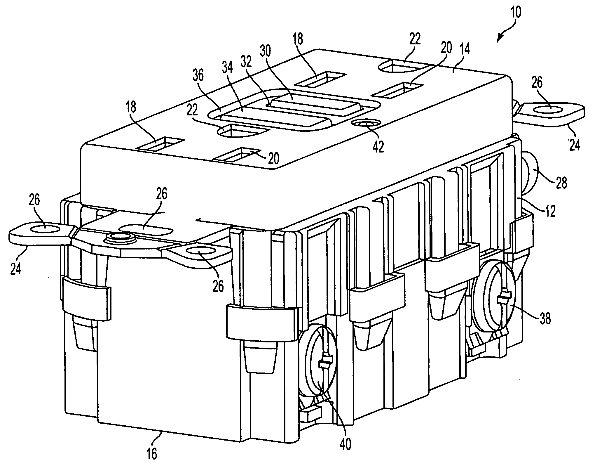
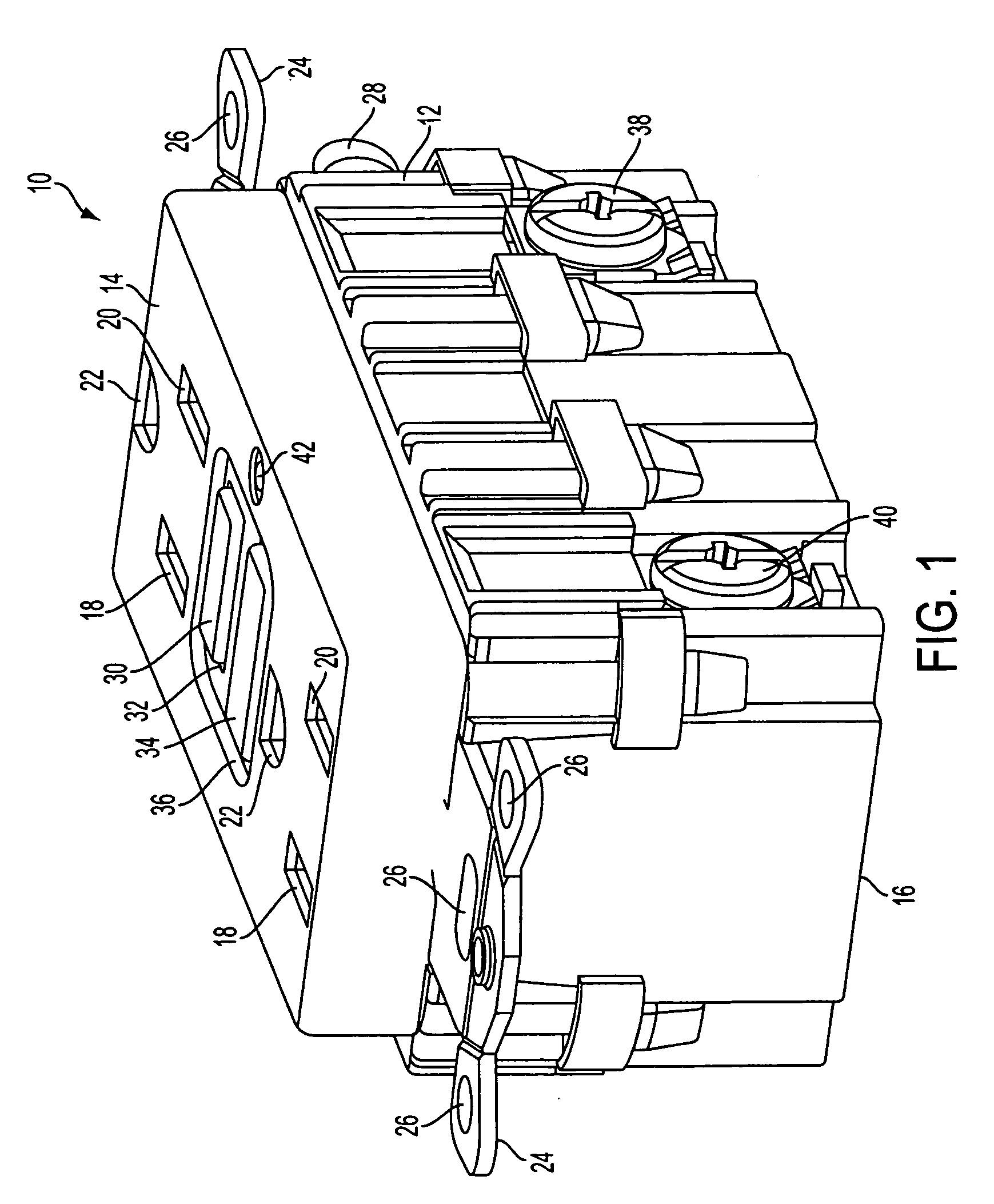
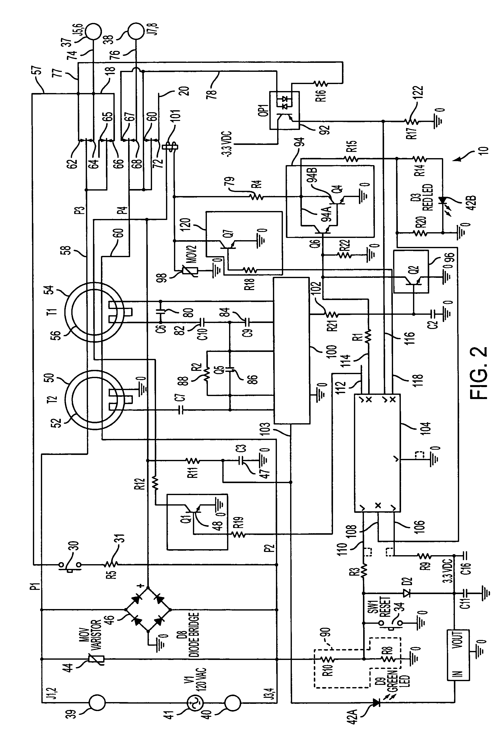
[0025]FIG. 1 is a perspective view of an exemplary fault indication and protection circuit 10 in accordance with an embodiment of the present invention. The fault indication and protection circuit 10 can be a ground fault circuit interrupter (GFCI), an arc fault circuit interrupter (AFCI) and / or perform the functions of both an AFCI and GFCI. However, for purposes of illustration, the fault indication and protection circuit 10 will be described as a GFCI device 10. The GFCI device 10 comprises a housing 12 having a cover portion 14 and a rear portion 16. The GFCI device 10 also includes a barrier between the cover portion 14 and the rear portion (e.g., FIGS. 12 and 13) when the cover portion 14 is removed from the rear portion 16. The cover portion 14 and rear portion 16 are removably secured to each other via fastening means such as snaps, barbs, clips, screws, brackets, tabs and the like. The cover portion includes face receptacles (also known as plug / blade slots) 18 and 20 and gr...


PUM


Abstract

A self testing fault detector having a line side and a load side and a conductive path there between. The apparatus includes a solenoid, which is adapted to move a plurality of contacts disposed in the conductive path from a first position to a second position when the self testing device is powered from the line side; and a processor, which is adapted to energize the solenoid using a first switch and maintain said solenoid in the energized state using a second switch.

Description

CROSS-REFERENCE TO RELATED APPLICATION [0001] Related subject matter is disclosed in U.S. Non-provisional Patent Application of John R. Baldwin et al., filed on Jun. 16, 2003, Ser. No. 10 / 461,874, entitled “SELF TESTING GROUND DIGITAL FAULT INTERRUPTER”, U.S. Non-provisional Patent Application of John R. Baldwin et al. entitled “SELF TESTING GROUND FAULT CIRCUIT INTERRUPTER (GFCI) WITH END OF LIFE (EOL) DETECTION THAT REJECTS FALSE EOL INFORMATION”, filed even date herewith (attorney reference no.: 49380), U.S. Non-provisional Patent Application of Stephen M. Liscinsky III entitled “SELF TESTING GROUND FAULT CIRCUIT INTERRUPTER (GFCI) END OF LIFE (EOL) STATUS INDICATOR”, the entire contents of said applications being incorporated herein by reference. FIELD OF THE INVENTION [0002] The present invention relates generally to a self testing fault interrupting device, such as a ground fault circuit interrupter or an arc fault circuit interrupter. More particularly, the present invention ...

Claims


Application Information

Patent Timeline
IPC IPC(8): H02H3/00
CPCH01H83/04H02H3/335H02H3/04H01H2071/044
Inventor BALDWIN, JOHN R.MORTUN, SORIN I.YU, DAMING
Owner HUBBELL INC
Learn More