Twin elevator systems

a technology of elevator system and elevator shaft, which is applied in the direction of elevator, sustainable building, agriculture tools and machines, etc., can solve the problems of unacceptable delays for passengers, addressing some challenges, and not being able to meet the needs of users, and achieving the effect of reducing the number of passengers

Inactive Publication Date: 2007-02-22
THYSSENKRUPP ELEVATOR AG (DE)
View PDF10 Cites 45 Cited by
  • Summary
  • Abstract
  • Description
  • Claims
  • Application Information

AI Technical Summary

Problems solved by technology

For example, a poorly designed elevator system may cause unacceptable delays for passengers trying to reach a desired floor.
These solutions, while relatively successful in addressing some of the challenges, may not be acceptable by the user.
These reasons may include a feeling of unease when elevators accelerate, doors quickly closing, or difficulties that may be experienced as the result of using a complicated system, where passengers may have to change one or several times to get to a desired floor.
Despite the mentioned optimization measures, it is evident that the largest part or portion of the elevator shaft is not used when the elevator car is in another part of the shaft.
However, some of the disadvantages of such a system are the large scale drives and power supplies that become necessary for accelerating such a large mass.
Also, as the cars are semi-connected, the delays for passengers waiting for other passengers to exit and enter the elevator may be more as a result of two floors being simultaneously served.
Moreover, the stories of the building would have to be virtually equidistant, which is an expensive objective to meet in a building.

Method used


Image

  • Twin elevator systems
  • Twin elevator systems
  • Twin elevator systems

Examples


Embodiment Construction

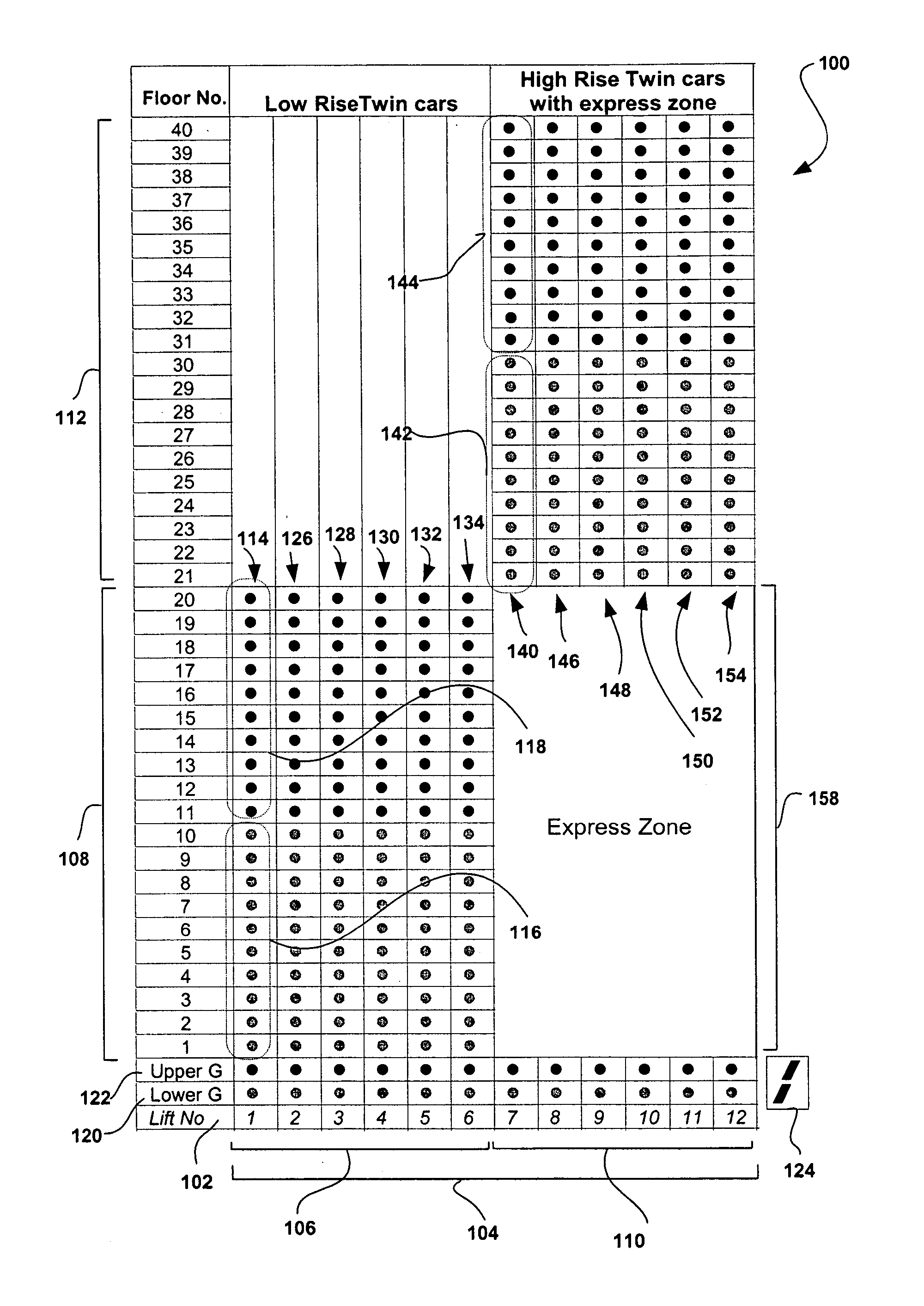
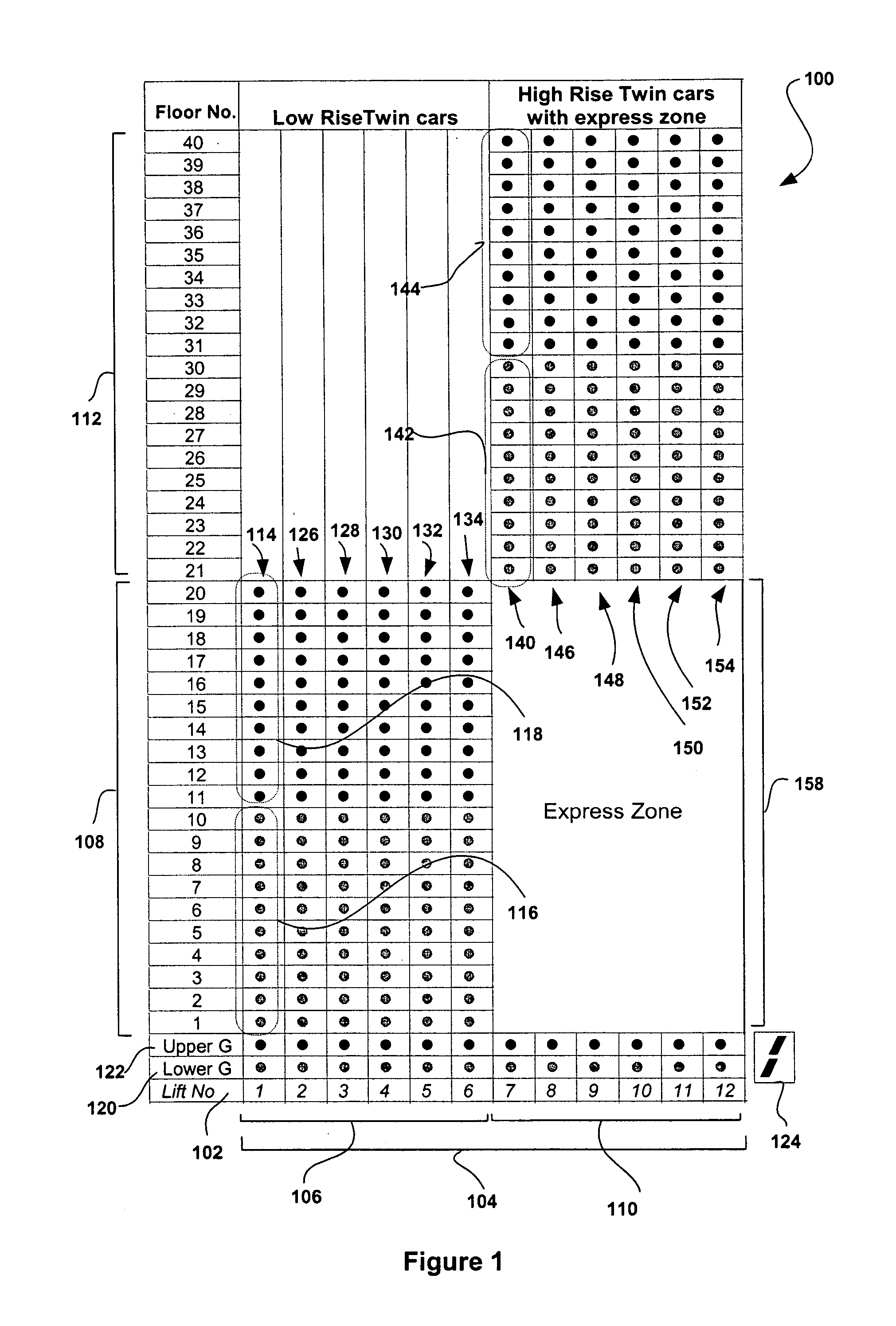
[0020]FIG. 1 illustrates an elevator system deployment scheme 100 employing two independently moving elevator cars (Twin Cars) operating within each elevator shaft according to an aspect of the present invention. The system 100 according to the present invention represents a zoned twin elevator system. Each elevator car or lift operates within an elevator shaft, where each shaft is designated by a lift number 102 (e.g., 1-12). Elevator shafts 1-12, as indicated by 104, are illustrated at the bottom of deployment scheme 100, where a first group of elevator shafts, indicated by 106, provide transportation services to a first region of floors within a building (e.g., floors 1-20), as indicated by 108. A second group of elevator shafts, indicated by 110, similarly provide transportation services to a second region of floors with the building (e.g., floors 21-40), as indicated by 112.

[0021] Within the first group of elevator shafts, indicated by 106, elevator shaft 114 comprises a twin ...


PUM


Abstract

An elevator system comprises at least two independently operable elevator cars in each of a plurality of elevator shafts within a building. The elevator system comprises at least one first elevator shaft having a lower first and a lower second region, where a first elevator car moves within the lower first region of the first elevator shaft and a second elevator car moves within the lower second region. The first and second elevators are moveably controlled independently of each other within the first shaft. The system also includes at least one second elevator shaft having an upper first and an upper second region, where a third elevator car moves within the upper first region of the second elevator shaft and a fourth elevator car moving within the upper second region. The third and fourth elevator cars also are moveably controlled independently of each other.

Description

FIELD OF THE INVENTION [0001] The present invention relates to systems and methods of deploying elevator systems, in particular, the deployment of a plurality of deployment schemes associated with twin elevator systems. BACKGROUND OF THE INVENTION [0002] In multi-storey buildings, one of the main objectives is to efficiently transport passengers to various floors using an elevator system. In designing, developing, and deploying elevator systems, particular attention should be paid to the portion of the building core that is dedicated to the elevator system. For example, as the number of elevator shafts are increased to meet the demands of higher buildings, maximizing real estate space as a commodity is also a main concern that must be addressed. Therefore, the object is to try and minimize the required number of elevator shafts that are deployed within an elevator system, while also trying to effectively meet the transportation needs of passengers and freight within the building. Fo...

Claims


Application Information

Patent Timeline
Patent Type & Authority Applications(United States)
IPC IPC(8): B66B1/20
CPCB66B1/18B66B1/2466B66B9/00B66B2201/301B66B1/468B66B2201/305B66B2201/306Y10S187/902B66B2201/303Y02B50/00
Inventor SMITH, RORY S.HUFF, RANDOLPH W.PETERS, RICHARD D.POWELL, BRUCETHUMM, GERHARD
Owner THYSSENKRUPP ELEVATOR AG (DE)
Why Eureka
Try Eureka