Search coil mount for facilitating inspection of a generator rotor in situ

a generator rotor and coil mount technology, applied in the direction of motor/generator/converter stopper, dynamo-electric converter control, instruments, etc., can solve the problems of destroying symmetry, requiring substantial modification of the generator, and requiring no longer identical flux waves of the different poles

Active Publication Date: 2007-02-22
SIEMENS ENERGY INC
View PDF7 Cites 2 Cited by
  • Summary
  • Abstract
  • Description
  • Claims
  • Application Information

AI Technical Summary

Problems solved by technology

However, if for example, two or more turns in one pole of the winding become shorted together, or if a ground fault occurs in the winding, this symmetry is destroyed and the flux waves of the different poles are no longer identical.
However, among the disadvantages associated with known search coil installations are the fact that they are complex in design, require multiple components, and generally require that the rotor be removed from the generator in order to install the search coil, that the search coil or flux probe be pre-installed at the time of initial manufacture of the generator, or that a substantial modification be made to the generator subsequent to its manufacture.
Complex and numerous components are cost intensive as is the need to substantially modify the generator in order to install the search coil, and removal of the rotor disadvantageously requires a prolonged maintenance outage.

Method used


Image

  • Search coil mount for facilitating inspection of a generator rotor in situ
  • Search coil mount for facilitating inspection of a generator rotor in situ
  • Search coil mount for facilitating inspection of a generator rotor in situ

Examples


example

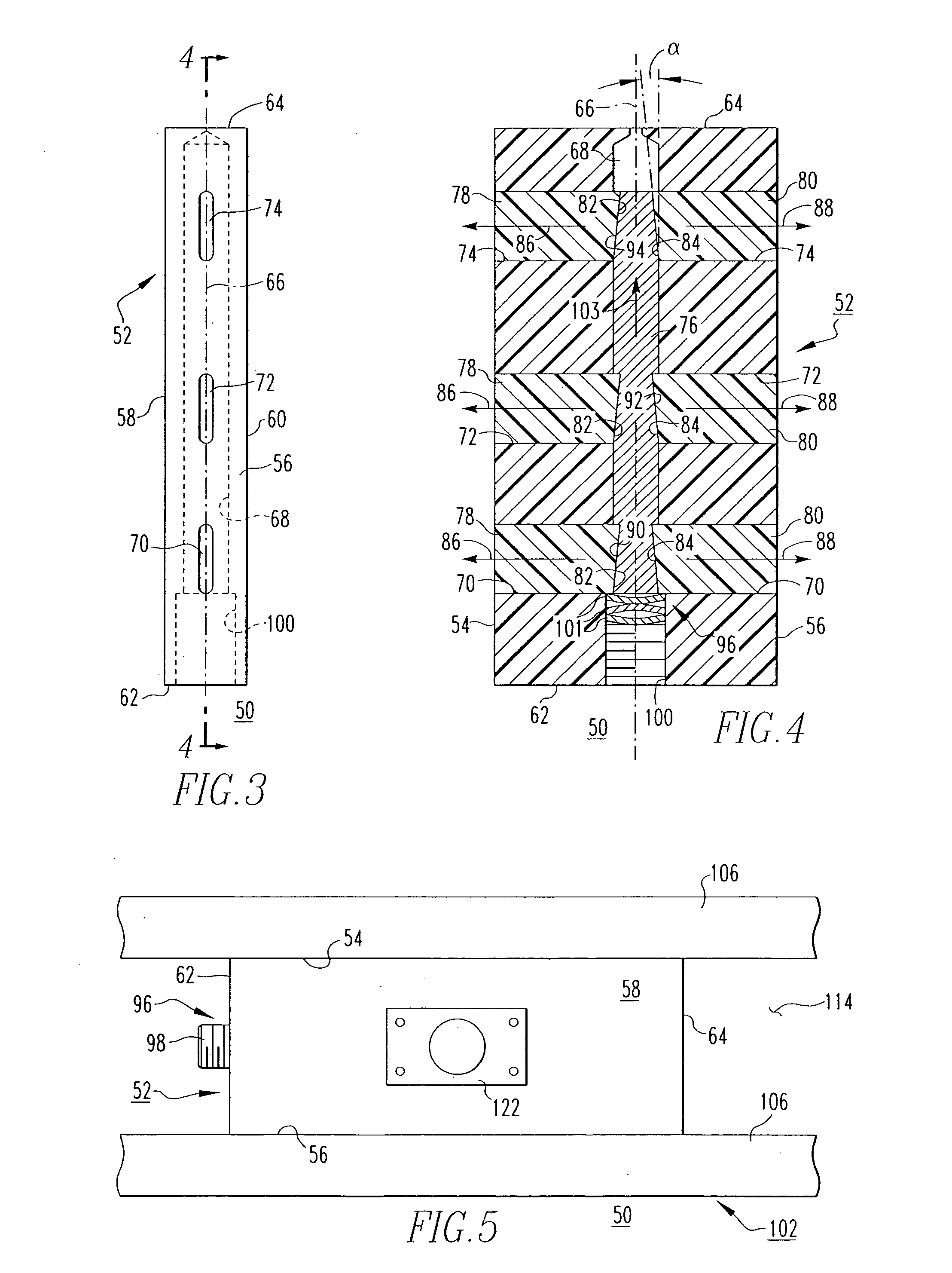
[0036] The aforementioned mount 50 was tested in order to simulate a typical electrical generator installation and to determine how well the mount 50 can withstand the forces commonly associated with such an application. Specifically, in a first test, the mount 50 was installed within a steel test block having sides and being designed to generally simulate the generator stator core slot (e.g., core slot 114 of FIG. 5). The wedge pin 76 was installed in longitudinal hole 68 and the tightening screw or set screw 98 was tightened, as previously described, to a force of 5 ft-lb. The test piece was then loaded in shear and thermal cycled from about −10° F. (−23° C.) to about 212° F. (100° C.).

[0037] The break-away force or force at which the block 52 first began to slide within the steel test block, was about 839 pounds (381 kilograms). After three thermal cycles, the set screw 98 was retightened to compensate for creep (e.g., movement of the block 52). Prior to such retightening, the b...


PUM


Abstract

A mount is for installing a probe, such as for example, a search coil, in a variety of locations and orientations within an electrical generator, without requiring the rotor of the generator to be removed. The mount includes a block having a longitudinal hole and a plurality of transverse slots intersecting the hole. A plurality of wedges are disposed within the slots. A wedge pin inserted into the longitudinal hole engages the wedges forcing the wedges outward in order to secure the mount and search coil thereon in the desired position within the generator, such as for example, in the air gap between the rotor and stator. A fastening mechanism further secures the mount in place.

Description

BACKGROUND OF THE INVENTION [0001] 1. Field of the Invention [0002] The present invention relates generally to the inspection of electrical generators and, more particularly, to a mount for installing a search coil in or about the air gap between the rotor and the stator of an electrical generator without requiring removal of the rotor. [0003] 2. Background Information [0004] Electrical generators, such as, for example, large turbine generators, must be routinely inspected to assure optimum performance and safe operating conditions. [0005]FIGS. 1 and 2 show a representative example of a turbine generator 2. The generator 2 generally includes an outer housing 4 which encloses an annular stator 6 and a rotor 8. Typically, the housing 4 is airtight and contains a coolant gas, such as hydrogen, which is circulated throughout the generator 2. The annular stator 6 is supported in a frame 10 within housing 4 and includes a stator or armature winding 12 which is disposed in slots 14 (FIG. 2...

Claims


Application Information

Patent Timeline
Patent Type & Authority Applications(United States)
IPC IPC(8): G01R31/06G01R31/34H02K11/00
CPCG01R31/346H02K3/487H02K11/20
Inventor DAILEY, GEORGE F.O'LEARY, MICHAEL
Owner SIEMENS ENERGY INC
Why Eureka
Try Eureka