Fixing device and image forming apparatus

a technology of fixing device and image forming apparatus, which is applied in the direction of electrographic process apparatus, instruments, optics, etc., can solve the problems scratching of image formed on the sheet, and creating image abrasion (guiding trace) on the outer surface of the image on the sheet, so as to suppress the effect of reducing image quality

Inactive Publication Date: 2007-03-01
KYOCERA DOCUMENT SOLUTIONS INC
View PDF8 Cites 17 Cited by
  • Summary
  • Abstract
  • Description
  • Claims
  • Application Information

AI Technical Summary

Benefits of technology

[0011] In view of the problems residing in the prior art, an object of the present invention is to provide a fixing device which can suppress redu

Problems solved by technology

However, since the separating claw guides the sheet while separating it as described above, there are cases where an image formed on the sheet is scratched by the separating claw.
This causes a problem of creating image abrasion (guiding trace) on the outer surface of the image on the sheet.
However, this patent publication discloses no member for actively guiding the sheet separated by the separating claw toward the rotary member.
Accordingly, in the case where a separating claw 70 and a roller member (rotary member) 80 are arranged, for example, to have such a positional relationship

Method used


Image

  • Fixing device and image forming apparatus
  • Fixing device and image forming apparatus
  • Fixing device and image forming apparatus

Examples


first embodiment

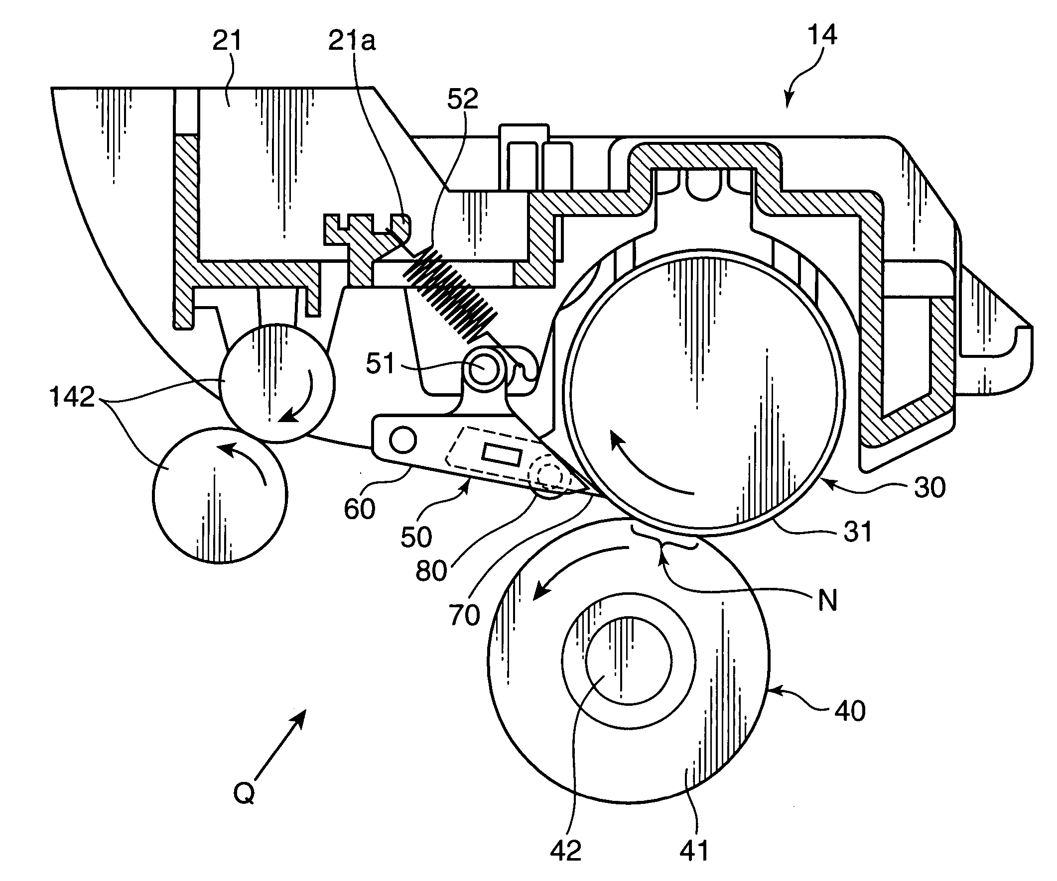
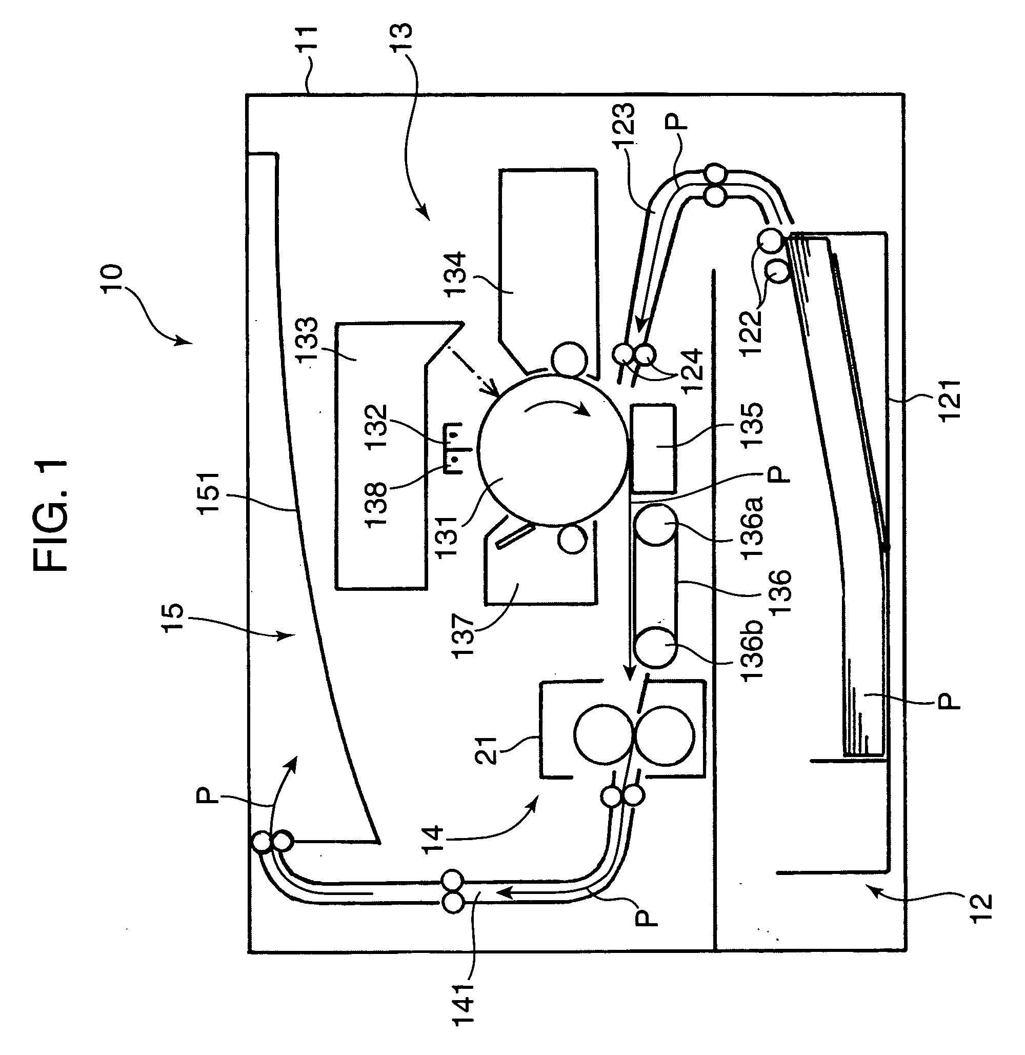
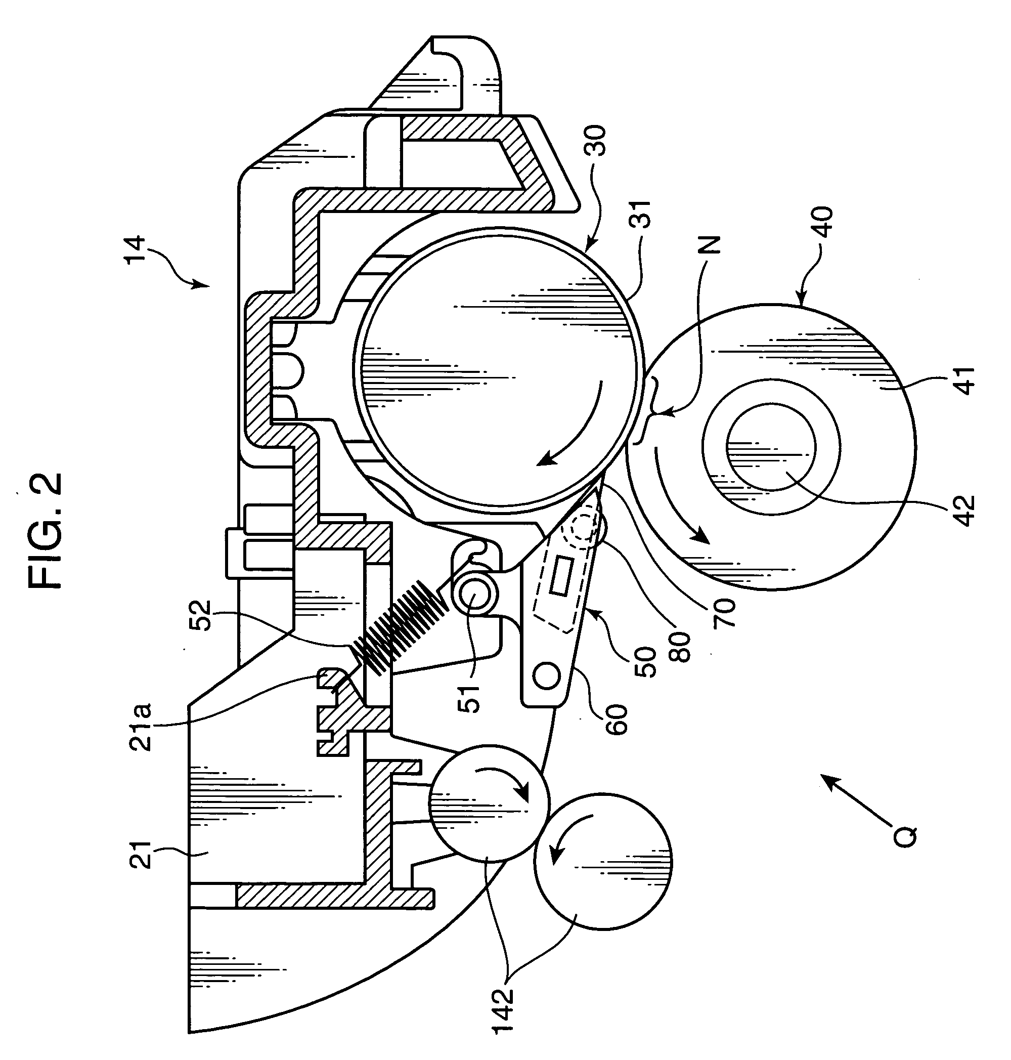
[0039]FIG. 1 is a view showing the entire construction of a printer including an image fixing unit according to one embodiment of the invention, and FIGS. 2 to 6 are views showing the construction of the image fixing unit according to a first embodiment of the present invention. First with reference to FIG. 1, the entire construction of the printer 10 including the image fixing unit 14 according to the first embodiment of the present invention is described. It should be noted that the image fixing unit 14 is one example of a “fixing device” of the present invention.

[0040] As shown in FIG. 1, in the printer 10 of this embodiment, a sheet storing unit 12 for storing a stack of sheets (recording sheets) P to which printing is applied, an image forming unit 13 for transferring images to the sheets P dispensed one by one from a bunch of sheets stored in the sheet storing unit 12, and an image fixing unit 14 for fixing the image transferred to the sheet P in the image forming unit 13 to ...

second embodiment

[0093] Next, a separating mechanism according to a second embodiment of the present invention is described. In the second embodiment, the tip of the above claw member has a specified width in a rotational axis direction of the fixing roller, and one rotary member (roller member) is arranged within an area extending downstream from the tip of the claw member along the conveyance path while having this width.

[0094]FIG. 8 is a view showing the fixing roller 30 and the image fixing unit 14 shown in FIG. 2 and separating mechanisms 50A according to the second embodiment when viewed in the direction of arrow Q, FIG. 9 is a plan view showing the construction of the separating mechanism 50A according to the second embodiment, FIG. 10 is a plan view showing an exploded state of the separating mechanism 50A, and FIG. 11 is a front view of the separating mechanism 50A.

[0095] Similar to the separating mechanisms 50 according to the first embodiment (see FIG. 3), four separating mechanisms 50A...

third embodiment

[0116] Next, a separating mechanism according to a third embodiment of the present invention is described. In the third embodiment, a claw member is so supported as to be freely movable in directions about two axes, and the claw member is biased toward the outer circumferential surface of a fixing roller so that a tip portion of the claw member presses the fixing roller. Here, as examples of the above “directions about two axes”, the claw member is so supported as to pivot in a first direction about an axis substantially parallel to the central axis of the fixing roller and in a second direction about an axis substantially normal to the central axis of the fixing roller.

[0117]FIG. 14 is a section showing a separating mechanism 50B according to the third embodiment of the present invention and a fixing roller 30, FIG. 15 is a plan view showing the construction of the separating mechanism 50B, FIG. 16 is a plan view showing an exploded state of the separating mechanism 50B, FIG. 17 i...


PUM


Abstract

A fixing device includes a fixing roller for fixing a toner image transferred onto a sheet and conveying the sheet along a conveyance path, and a separating mechanism for separating the sheet from the fixing roller. The separating mechanism includes a claw member having a tip portion in contact with the outer circumferential surface of the fixing roller to separate the sheet from the fixing roller, a holder member for holding the claw member, and a rotary member rotatably held in the holder member downstream of the tip portion relative to the conveyance path and adapted to guide the sheet separated from the fixing roller to a downstream side along the conveyance path while being rotated. The holder member has a guiding portion for guiding the sheet to the rotary member on the conveyance path between the tip portion of the claw member and the rotary member.

Description

BACKGROUND OF THE INVENTION [0001] 1. Field of the Invention [0002] The present invention relates to a fixing device for fixing a toner image transferred onto a sheet and an image forming apparatus employing such a fixing device. [0003] 2. Description of the Related Art [0004] There have been conventionally known image forming apparatuses constructed such that an electrostatic latent image on the outer circumferential surface of a photoconductive drum is developed with toner to form a toner image, and an output image is obtained by transferring this toner image to a sheet. There have been also known fixing devices installed in such image forming apparatuses to fix a toner image transferred onto a sheet. [0005] A conventional fixing device is provided with a fixing (heat) roller for heating a sheet and a pressure (press) roller for pressing the sheet against the fixing roller while defining a nip area in cooperation with the fixing roller. In the fixing device constructed in this way...

Claims


Application Information

Patent Timeline
IPC IPC(8): G03G15/20
CPCG03G15/2028
Inventor KANEMATSU, YOSHIHARUNAKANO, KUNIAKIUCHIDA, SHINICHI
Owner KYOCERA DOCUMENT SOLUTIONS INC
Why Eureka
Try Eureka