External fixation system and method of use

a fixation system and external technology, applied in the field of external fixation system and device, can solve the problems of improper adjustment, slow and difficult adjustment in incremental and reliable fashion, non-compliance or deviation from the prescribed protocol, awkward adjustment mechanism, etc., and achieve the effect of distraction/reduction/compression of bone or bone segments

Active Publication Date: 2007-03-01
SYNTHES GMBH
View PDF26 Cites 77 Cited by
  • Summary
  • Abstract
  • Description
  • Claims
  • Application Information

AI Technical Summary

Benefits of technology

[0007] An external fixation system may include ring assemblies and / or ring segments which may be attached, for example, by one or more linear distractors, angular distractors and / or elongated members. The linear distractors may allow for incremental changes in distance between the ring assemblies and / or ring segments and, thus, may enable distraction / reduction / compression of bone or bone segments.
[0008] Each linear distractor may have a body portion, an adjustment knob and an elongated member (e.g., a threaded rod). The body portion may be attached to one ring assembly / segment, the elongated member may be attached to another ring assembly / segment. An end of the elongated member may be moveable positioned within the body portion. The knob may be connected to the body portion so that the knob may rotate relative to the body portion but may be fixed axially. Rotation of the knob may cause the elongated member to move relative to the knob and within the body portion. The body portion may have a window for viewing the position of an end of the elongated member within the body portion. The body portion may also have a gauge which may comprise a scale so as to provide the operator with a visual indication of the movement of the elongated member. Moreover, the knob may have a detent mechanism which may engage one or more indentations positioned around the body portion. Such a construction may provide tactile and / or audible indications to an operator of incremental movements of the distractor and, consequently, of the ring assemblies / segments relative to each other.
[0009] Selectively engageable fasteners may also be provided as part of an external fixation system and may allow for rapid assembly and adjustment of the external fixation system. In one embodiment, the selectively engageable fastener may be a nut which may have an axis, a first end, a second end and a bore extending from the first end to the second end. The bore may have an axis which may be oblique to the axis of the nut. The nut may have a first internal threaded portion proximate the first end, a second internal threaded portion proximate the second end and an unthreaded portion between the first and second ends. The nut may be configured such that alignment of the axis of the bore with the axis of a threaded rod may enable an operator to quickly move the nut along the axis of the rod without the need to rotate the nut. In such an orientation, the threaded portions of the nut may not engage the threads of the rod. Alignment of the axis of the nut with the axis of the rod may result in the internal threaded portions of the nut engaging the external threads of the rod so that the nut may be rotated on the rod and tightened against a component of the external fixation system such as a ring assembly / segment. In an alternative embodiment, the threaded portions may be configured in such a way that alignment of axis of the nut with the axis of the rod may allow for quick axial movement of the nut whereas alignment of the axis of the bore with the axis of the rod may engage the threaded portions of the nut with the threads of the rod.

Problems solved by technology

Existing distraction / reduction / compression devices employ adjustment mechanisms which may be awkward, slow and difficult to adjust in an incremental and reliable fashion.
However, the complexity of existing systems can often lead to improper adjustments, non-compliance or deviation from the prescribed protocol, and / or undue discomfort for the patient.

Method used


Image

  • External fixation system and method of use
  • External fixation system and method of use
  • External fixation system and method of use

Examples


Embodiment Construction

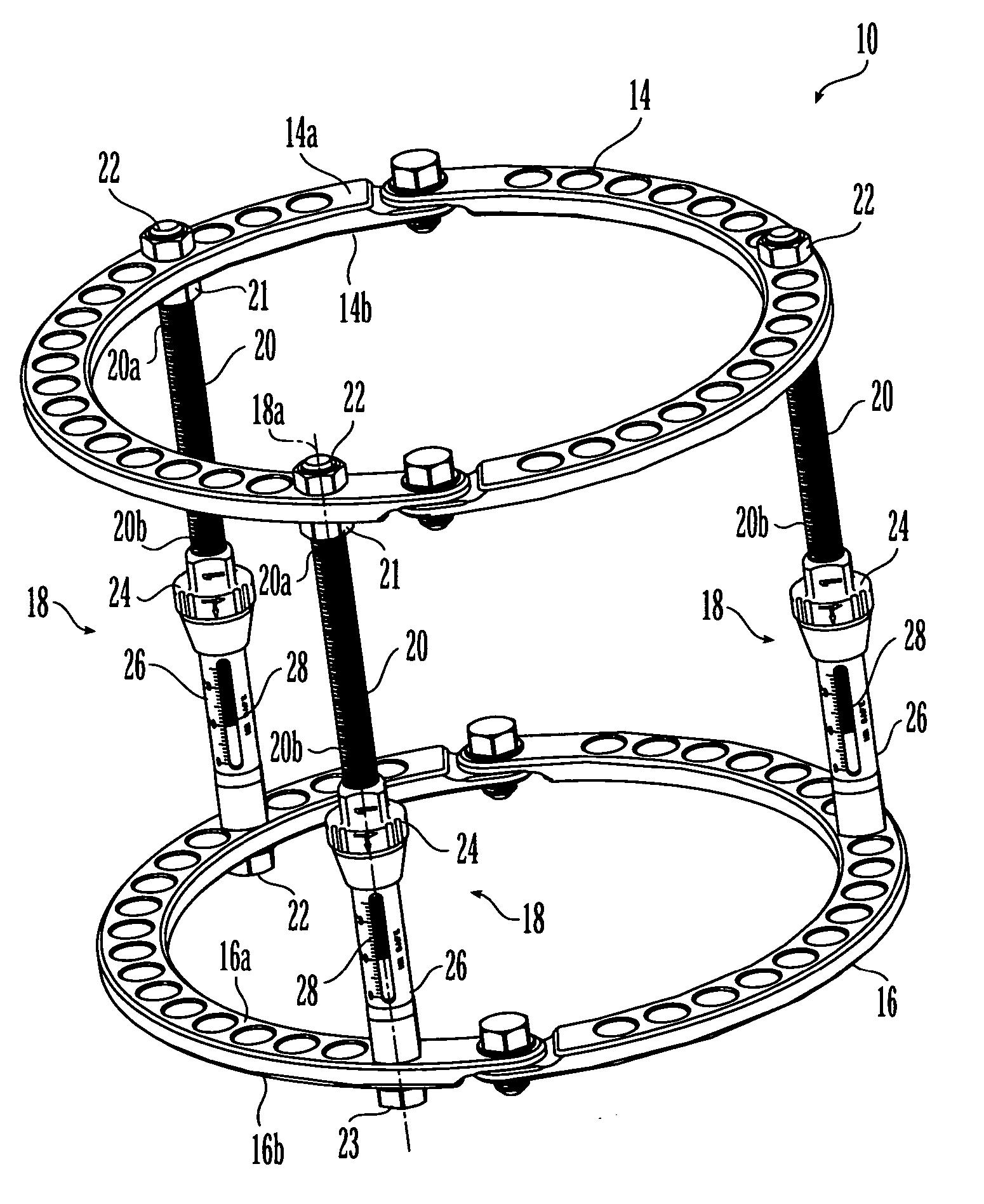
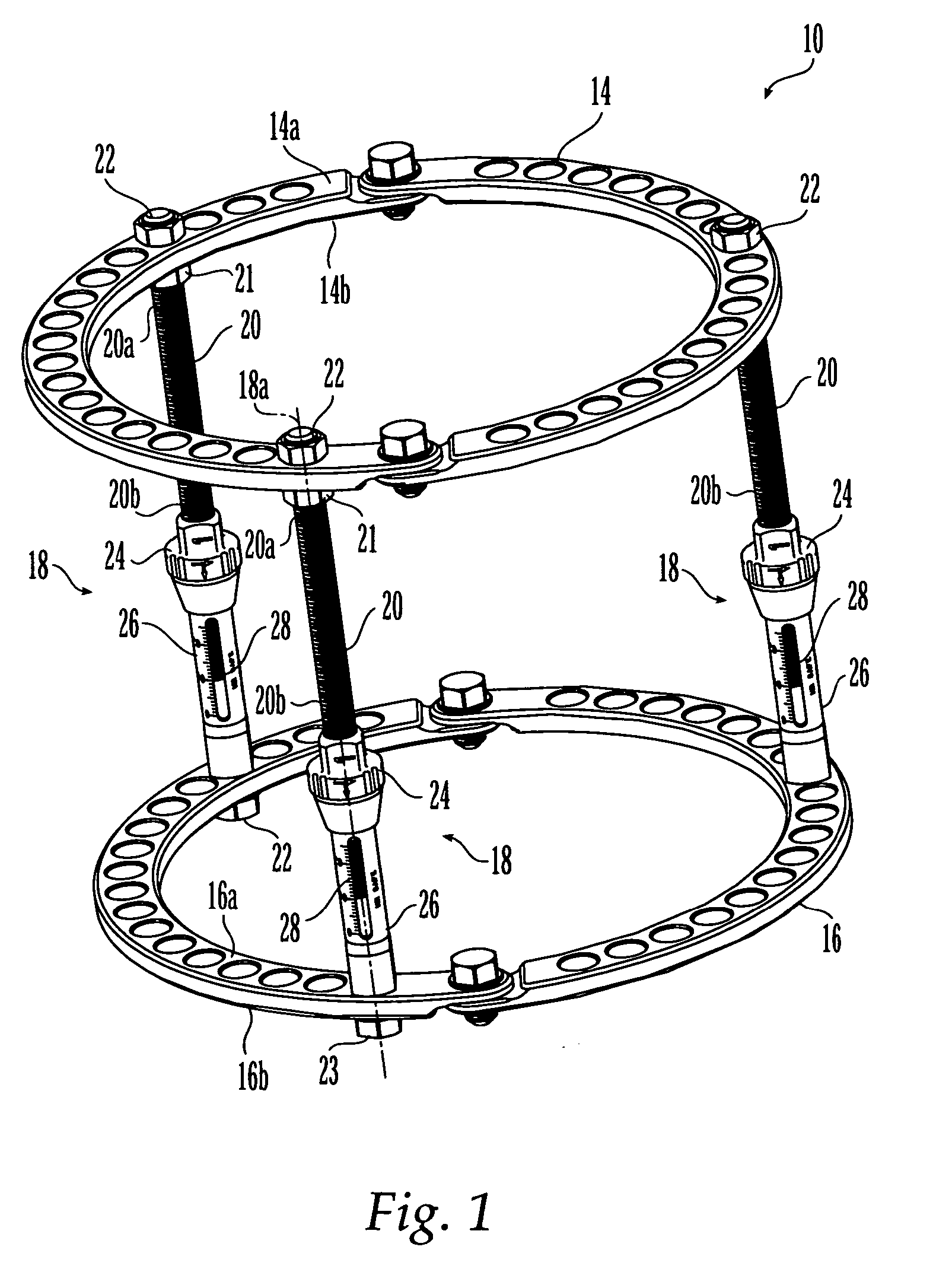
[0040] As shown in FIG. 1, the external fixation system 10 may include a first ring assembly 14 and a second ring assembly 16, which may be operably attached to and separated by one or more linear distractors 18. In some embodiments, the external fixation system 10 may have more than two ring assemblies. Moreover, in one preferred embodiment, three linear distractors 18 may be used to connect two ring assemblies (e.g., ring assemblies 14, 16), although other number of linear distractors may be used and other component in addition to or alternatively may be used to attach and separate ring assemblies, such as ring assembly 14, 16.

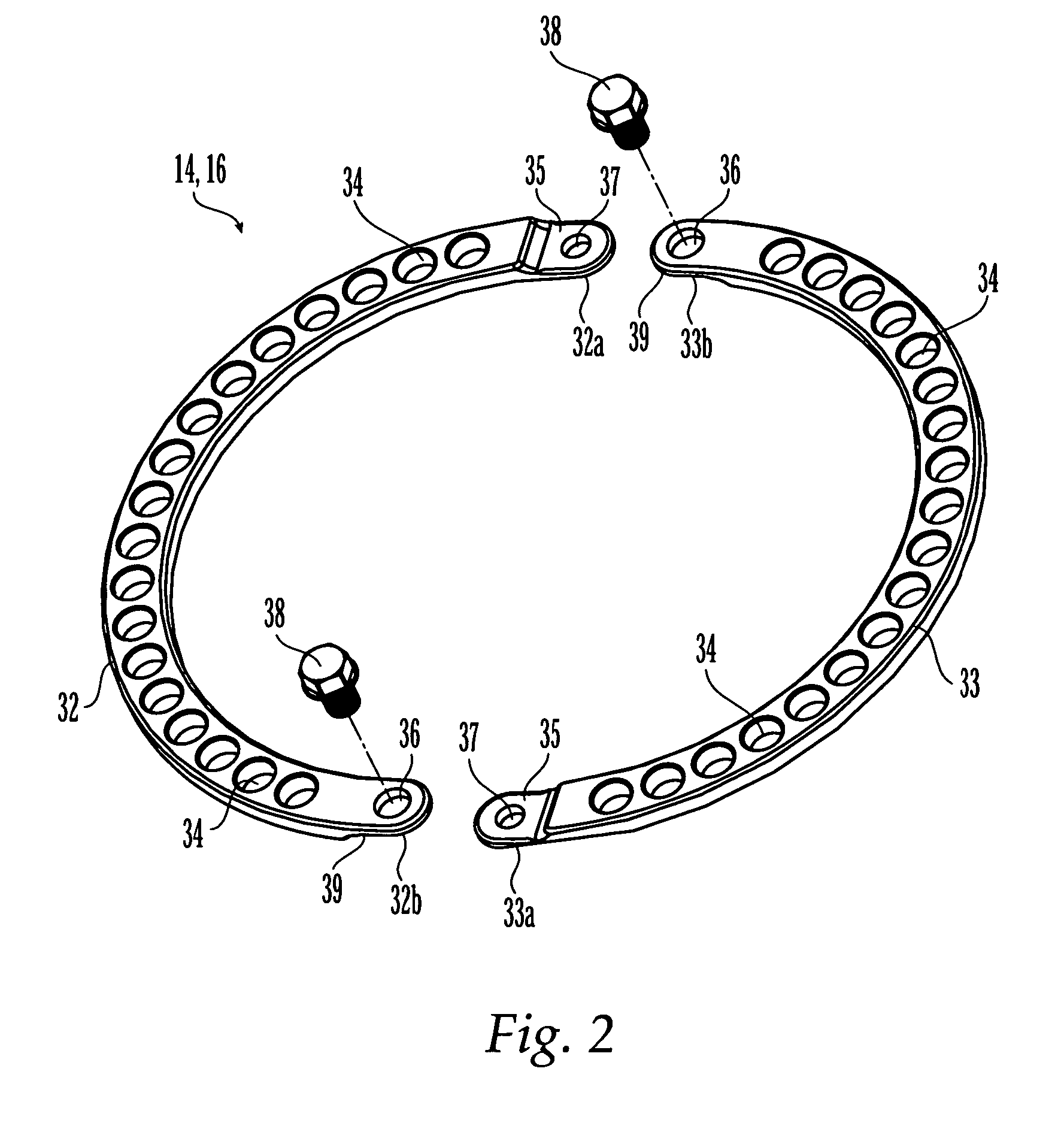
[0041]FIG. 2 illustrates that each ring assembly 14, 16 may be made of two or more ring segments 32, 33. Those skilled in the art will appreciate that the ring assemblies 14, 16 may be made of a single piece of material. A ring assembly 14, 16 may be sized and configured to be positioned entirely around a bone to form an external fixation system. It should ...


PUM


Abstract

An external fixation system for connecting one or more bone segments together to facilitate healing of bone. The system may include one or more rings and / or ring segments. One or more linear distractors and / or angular distractors may connect the rings to each other so as to allow for distraction and / or reduction / compression of a bone. Linear distractors may enable an operator to move the rings towards and away from each other, while angular distractors may enable an operator to angle the rings relative to each other. In an embodiment using angular distractors, one or more angular separation assemblies may be positioned between the rings. These separation assemblies may have joints which may two portions which may be angled relative to each other and connected directly or indirectly to the rings. Various fasteners (e.g., nuts) and / or tightening members may configured for quick movement along and selective tightening to various components. Moreover, clamps may be attached to the rings and may engage pins, wire, rods, which may be inserted into bone to hold bone segments to each other. The components of the external fixation system may be provided in sets or kits so that the a surgeon may select various combinations of components to create an external fixation system which is configured specifically for the particular needs of a patient and the bone fracture / deformity.

Description

FIELD OF THE INVENTION [0001] The present invention relates to bone fixation system and devices and, in particular, an external fixation device for stabilizing bone segments and promoting repair of bones and its method of use. BACKGROUND OF THE INVENTION [0002] External fixation devices are used to stabilize bone segments and to facilitate the healing of bones at a bone repair site. As used herein “bone repair site” refers to any bone region which is bounded on at least one side by a relatively healthy bone region to which orthopedic devices can be secured, such as an osteotomy defect or a fracture. Distraction and reduction / compression devices may be incorporated into an external fixation device and may be used to gradually adjust the relative orientation and spacing of the bone parts on opposing sides of a bone repair site. [0003] External fixation devices traditionally include a bar(s), rod(s) and / or arcuate ring(s) as well as transcutaneous pins, screws and / or wires, which are i...

Claims


Application Information

Patent Timeline
Patent Type & Authority Applications(United States)
IPC IPC(8): A61B17/00
CPCA61B17/66A61B17/62A61B17/56A61B17/58A61B17/64
Inventor HEARN, JIMMAUGHAN, THOMAS J.HORAN, TIMOTHY J.WAHL, MICHAEL J.
Owner SYNTHES GMBH
Why Eureka
Try Eureka