Systems and Methods for Non-Perpendicular Ultrasonic Plastic Welding

a technology of ultrasonic welding and plastic sheets, applied in the direction of lamination apparatus, layered products, chemistry apparatus and processes, etc., can solve the problems of deterioration of the performance of such a system, difficult to achieve consistent quality, and excessive melting of thin plastic sheets with energy applied

Inactive Publication Date: 2007-03-08
MOGADAM SAEED +3
View PDF3 Cites 6 Cited by
  • Summary
  • Abstract
  • Description
  • Claims
  • Application Information

AI Technical Summary

Problems solved by technology

While a plunge-weld system such as system 400 can perform well in many situations involving the welding of plastic sheets, the performance of such a system has been observed to deteriorate when welding plastic sheets having a thickness of less than about 5-6 mils (0.13-0.15 mm).
It can be difficult to achieve consistent quality in such welds because the ultrasonic energy delivered in the plunge weld configuration can cause thin plastic sheets to which the energy is applied to melt excessively, often destroying the material at the seam or cutting through it, rather than creating a strong bond.
Although the extent of the melting caused by the welding can be controlled for non-moving sheets by controlling the power level at which the ultrasonic welder operates, such a solution is not always feasible for continuous welding of moving materials.
Thus, achieving precise control of applied power to obtain a high-quality continuous weld can be difficult.
Similar difficulties can arise for those applications that involve the formation of tubes from a single sheet, such as a single plastic sheet, that is to be welded onto itself.

Method used


Image

  • Systems and Methods for Non-Perpendicular Ultrasonic Plastic Welding
  • Systems and Methods for Non-Perpendicular Ultrasonic Plastic Welding
  • Systems and Methods for Non-Perpendicular Ultrasonic Plastic Welding

Examples


Embodiment Construction

[0023] Illustrative embodiments will now be described to provide an overall understanding of the disclosed systems and methods. Those of ordinary skill in the art will understand that the disclosed systems and methods can be adapted and modified to provide systems and methods for other applications, and that other additions and modifications can be made to the disclosed systems and methods without departing from the scope of the present disclosure. For example, features of the embodiments can be combined, separated, interchanged, and / or rearranged to generate other embodiments. Such modifications and variations are intended to be included within the scope of the present disclosure.

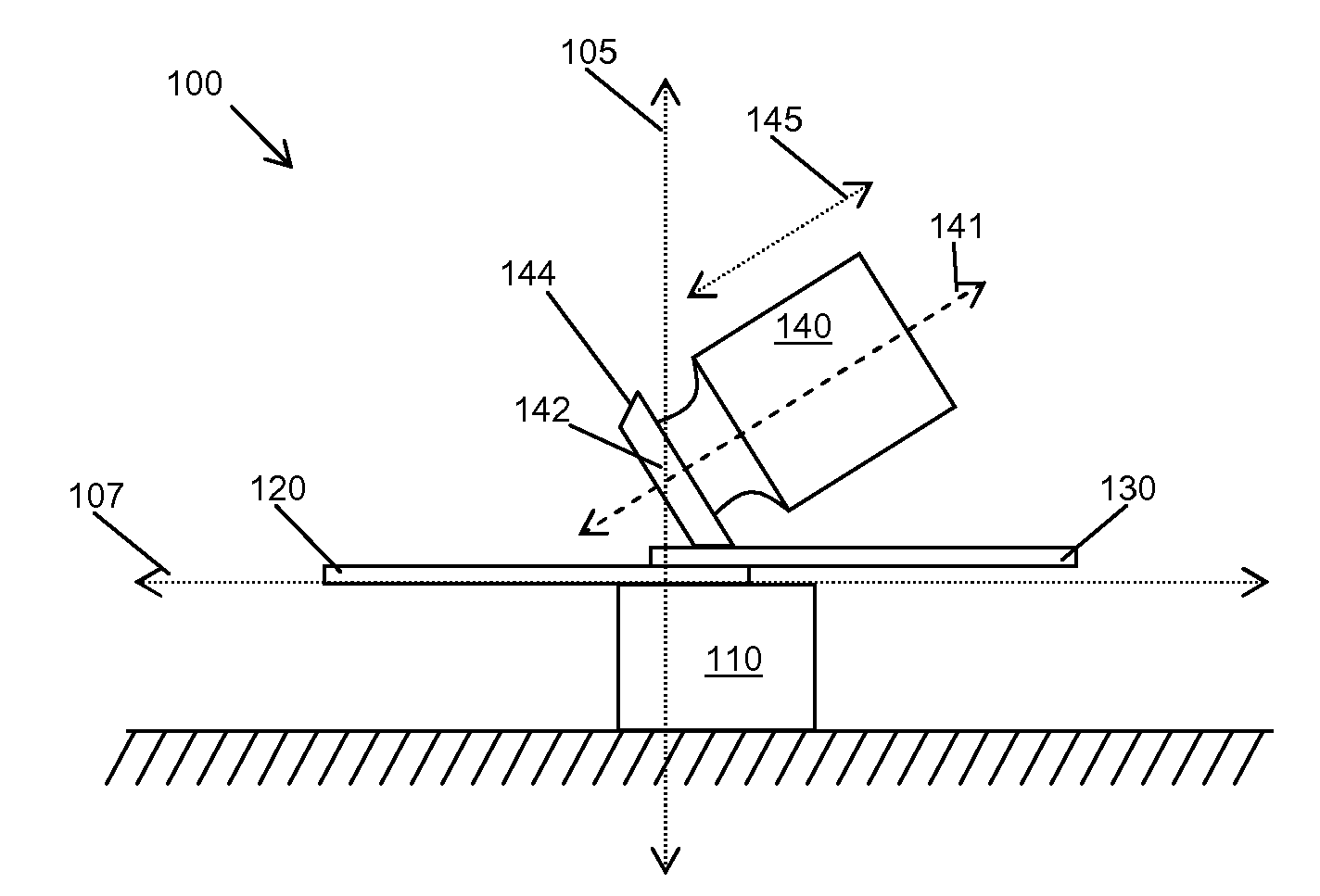
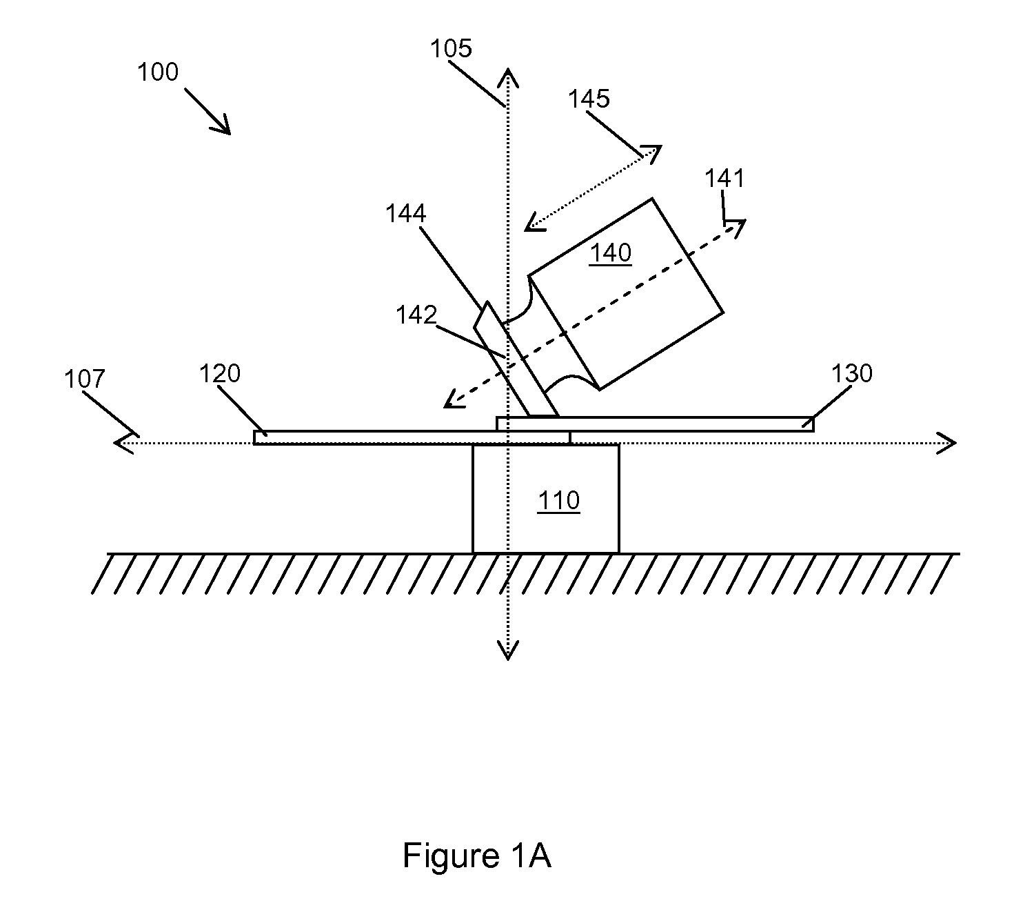
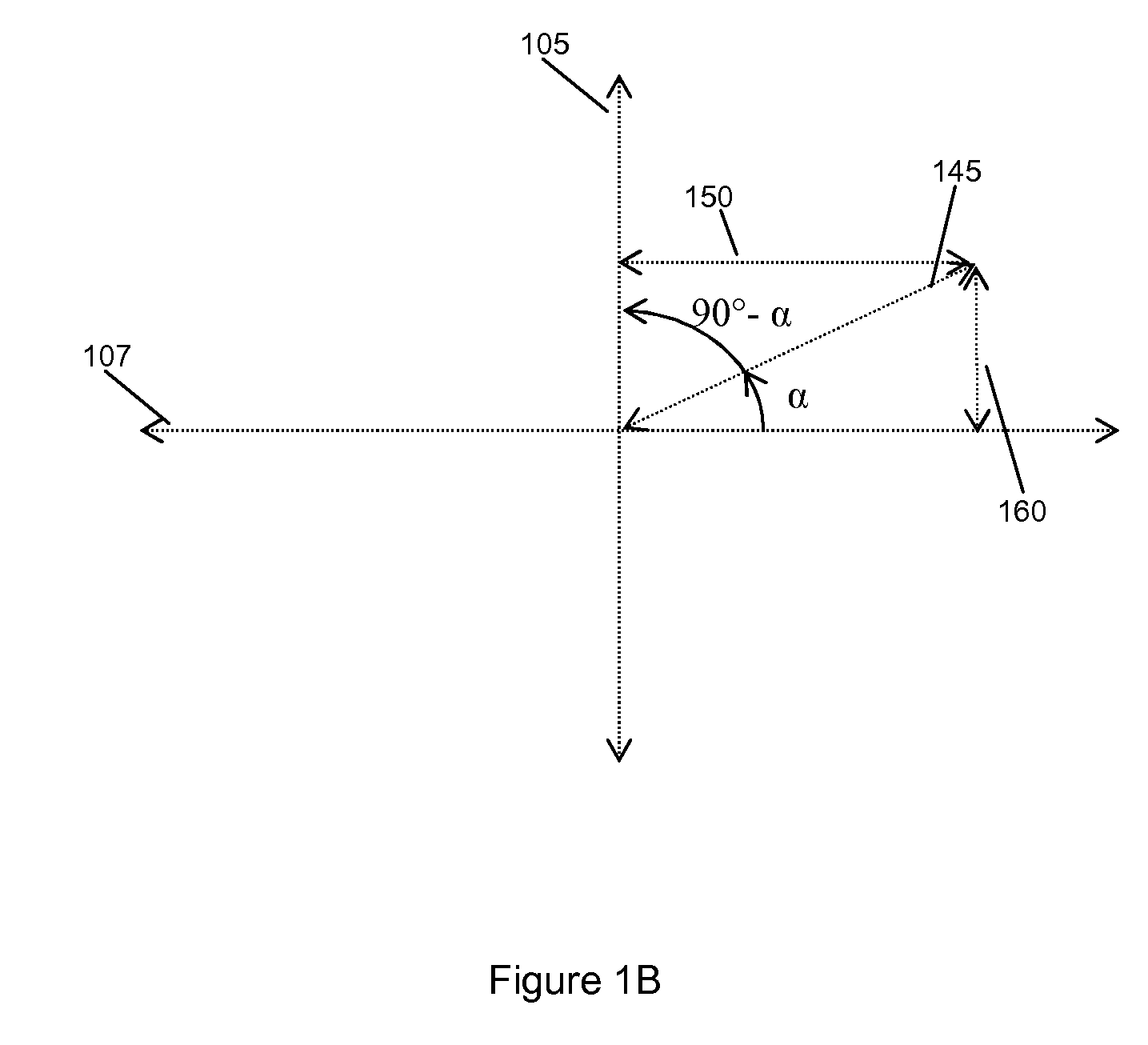
[0024]FIGS. 1A and 1B illustrate an exemplary system for ultrasonically welding plastic sheets. As shown in FIG. 1A, the system 100 includes an anvil 110 upon which the sheets 120, 130 are disposed and a sonotrode 140, having a working end 142, for delivering ultrasonic vibrations 145 to the sheets 120, 1...


PUM

PropertyMeasurementUnit
angleaaaaaaaaaa
angleaaaaaaaaaa
angleaaaaaaaaaa

Abstract

Systems for ultrasonically welding described herein include a sonotrode for delivering ultrasonic vibrations to two or more plastic sheets, so as to form a weld between them. The sonotrode and the plastic sheets are arranged such that the ultrasonic vibrations delivered by the sonotrode travel along a path that is oriented at an angle α with respect to a tangent to the surface being welded, wherein the angle α is less than 90 degrees. Methods for ultrasonically welding described herein include providing two or more plastic sheets to be welded together and delivering ultrasonic vibrations to form a weld between them, such that the ultrasonic vibrations travel along a path that is oriented at an angle α with respect to a tangent to the surface being welded, wherein the angle α is less than 90 degrees.

Description

REFERENCE TO RELATED APPLICATIONS [0001] This application claims the right of priority to U.S. Provisional Application No. 60 / 715,306, filed Sep. 8, 2005, which is hereby incorporated herein by reference.BACKGROUND OF THE INVENTION [0002] 1. Field of the Invention [0003] This disclosure related to systems and methods for the ultrasonic welding of plastic sheets. [0004] 2. Background Information [0005] A typical prior art system for ultrasonically welding plastic sheets is shown in FIG. 4A. As shown in FIG. 4A, a typical system 400 includes an anvil 410 upon which the sheets 420, 430 rest and a sonotrode 440 that delivers ultrasonic vibrations to the sheets 420, 430, so as to create a weld between them. The anvil 410 and the sonotrode 440 may be similar to devices described in U.S. Pat. Nos. 4,596,352, 4,646,957, 4,869,419, 5,941,443, and 6,079,608 and U.S. patent application Ser. No. 10 / 389,454, the contents of all of which documents are expressly incorporated by reference herein in...

Claims


Application Information

Patent Timeline
Patent Type & Authority Applications(United States)
IPC IPC(8): B32B37/00B32B37/06B29C65/00
CPCB29C53/40B29C66/81419B29C65/081B29C65/8207B29C65/8253B29C66/1122B29C66/43B29C66/4322B29C66/7352B29C66/83411B29K2023/06B29K2023/12B29K2025/00B29K2067/00B29K2077/00B29K2101/12B29C53/48B29C66/49B29C66/71B29C66/73921B29K2025/06
Inventor MOGADAM, SAEEDPATTEN, DONALDDIFINIZIO, TONYBEAM, SHANE
Owner MOGADAM SAEED
Why Eureka
Try Eureka