Post-tension cable wall stabilization

a technology of post-tension cable and wall structure, which is applied in the direction of building reinforcements, construction, building material handling, etc., can solve the problem of not yielding a finished structure with as strong structural integrity

Inactive Publication Date: 2007-03-15
KOHLER MICHAEL E
View PDF27 Cites 38 Cited by
  • Summary
  • Abstract
  • Description
  • Claims
  • Application Information

AI Technical Summary

Benefits of technology

[0006] The present invention provides architectural structures comprising: a) a footing portion having a portion which extends in a substantially-linear direction; b) a re-bar disposed within the footing portion; c) a plurality of courses of masonry units stacked upon on e another so as to form a wall structure having a top course, bottom course, and a length dimension, the wall structure being disposed above the footing portion. A portion of the masonry units include a vertically-oriented bore disposed through them, and are arranged in a manner sufficient to provide a plurality of vertical bores extending through the wall structure at periodical distances along the length dimension of the wall. The vertical bores extend from the footing portion and through at least the 3 lowermost courses of masonry units of the wall structure. There are also a plurality of tensioning cables, wherein each tensioning cable comprises: a first end portion; a second end portion; and a mid portion. The tensioning cables each further comprise: i) a first vertical portion extending through one of the vertical bo

Problems solved by technology

Many workers in the prior art have realized that merely stacking stones atop one another to form a wall structure, even when grouts or mortars are em

Method used


Image

  • Post-tension cable wall stabilization
  • Post-tension cable wall stabilization
  • Post-tension cable wall stabilization

Examples


Embodiment Construction

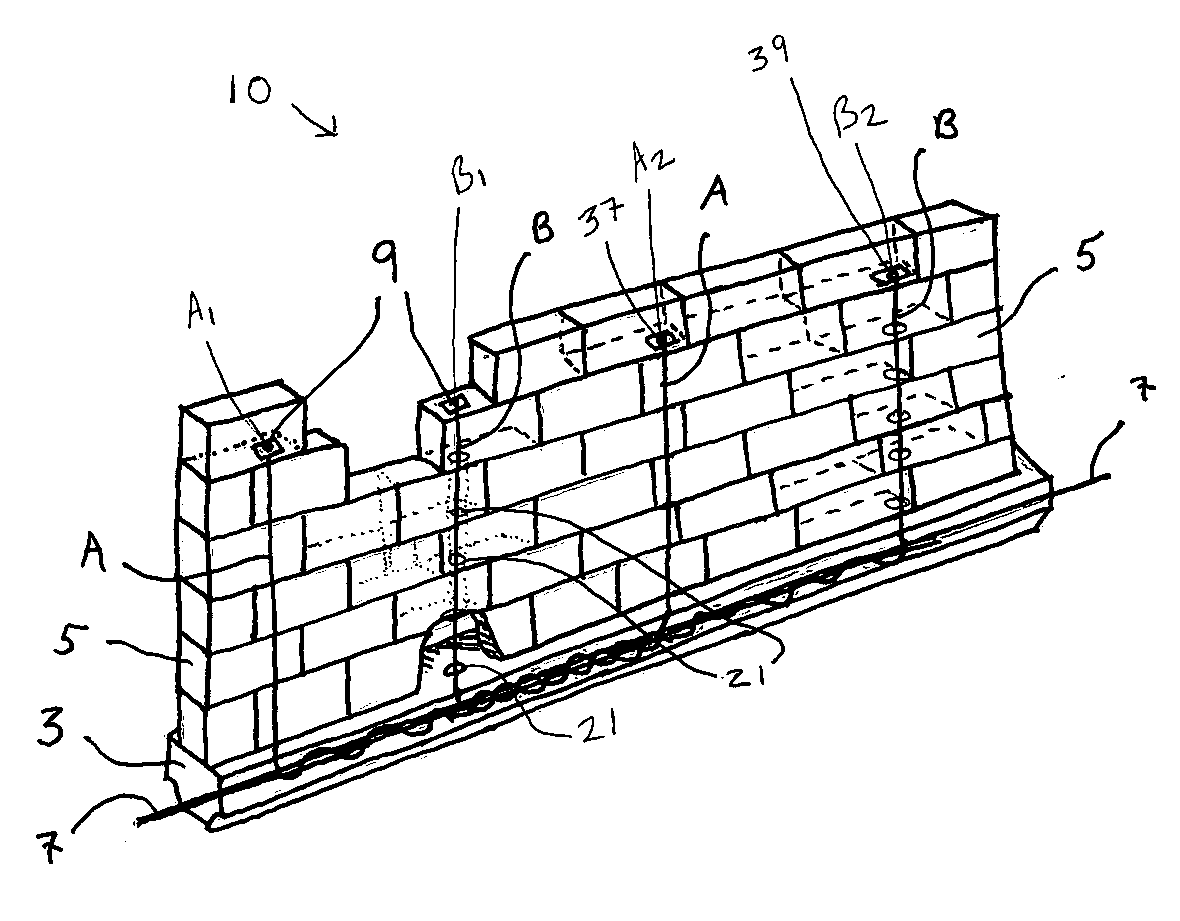
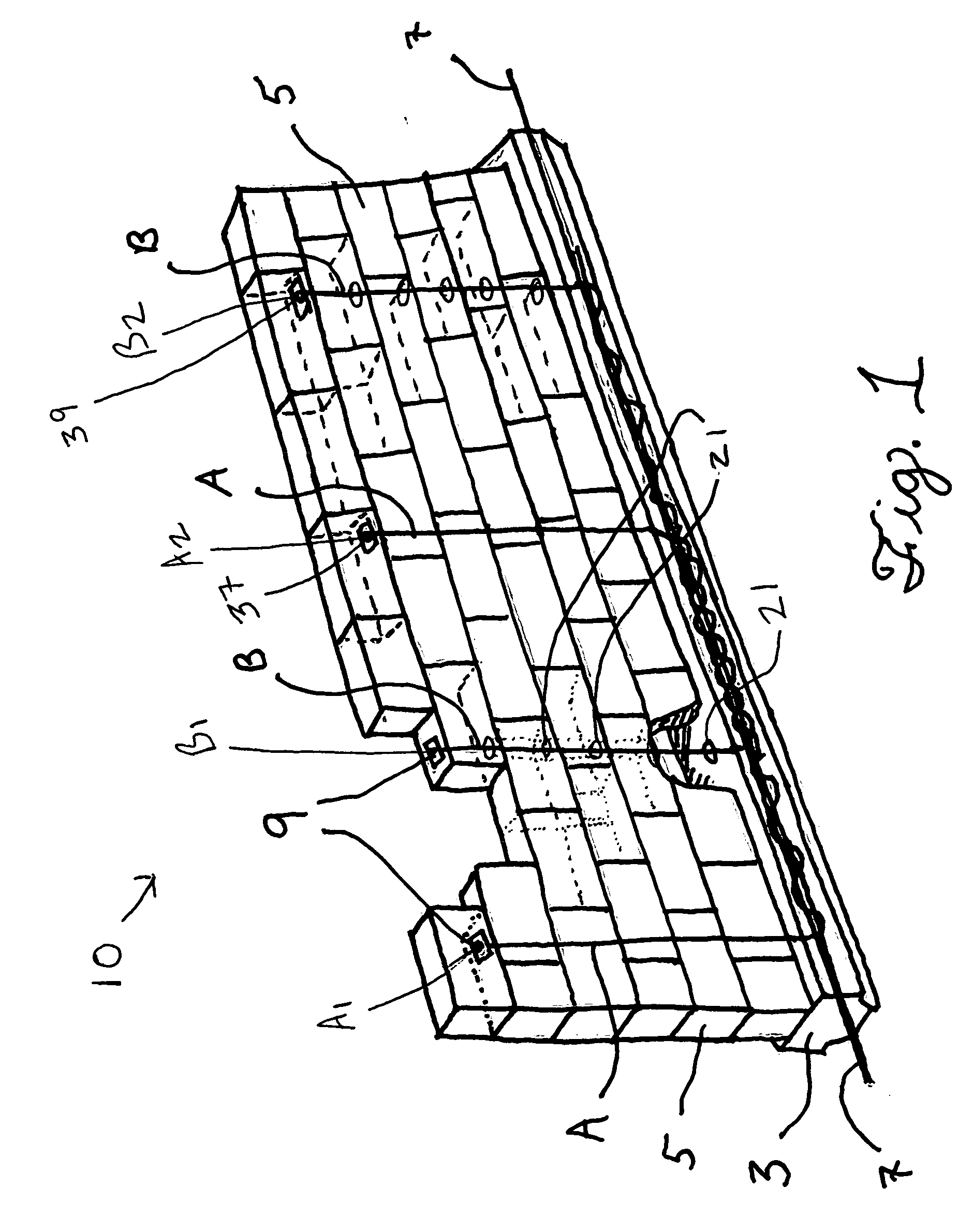
[0016] Referring to the drawings and initially to FIG. 1 there is shown an architectural structure in accordance with one embodiment of the invention. In this FIG. 1 is shown a wall 10 that comprises a plurality of courses of masonry units 5 stacked upon one another, and which are also preferably provided with a conventional mortar or other binding substance in the interstices between the individual masonry units 5 and layers thereof.

[0017] The masonry units 5 may be any material from which wall structures are known in the art to be comprised, including without limitation: clay-based bricks; concrete blocks; pieces or sections of natural stone; composite materials; wood; ceramic tiles; poured concrete; and glass blocks, etc.

[0018] The wall 10 is preferably built upon a footing material 3, which in one preferred embodiment is a poured mortar or concrete, as such concretes as from which footing materials may be poured are well-known in the art. To provide such a footing, a trench is...


PUM


Abstract

Provided herein are masonry structures, including walls, which are disposed upon a footing having a re-bar disposed longitudinally therethrough. The masonry structures of the invention include vertical bores disposed along their lengths, and include tensioned cables which extend through a first vertical bore, are spirally wound about the re-bar, and also extend through a second vertical bore such that the end portions are rigidly anchored in position near the top course of masonry units used in constructing the structures, and wherein the tensioned cables are under a relatively high mechanical tension. By staggering a plurality of tensioning cables, structures comprising a plurality of masonry units of enhanced structural stability over structures of prior art are provided.

Description

TECHNICAL FIELD [0001] This invention relates generally to architectural structures. More particularly, it relates to wall structures made from masonry materials, including natural stone, and to means for increasing the stability of such structures. BACKGROUND [0002] Wall structures made from masonry materials have been in use for centuries, with the famous Great Wall of China being a prime and popular example. Thus, it is well-known in the art to stack stones or like materials atop one another to provide wall structures, which structures may be from a few meters in length to several miles, and may vary in height from a few centimeters to several meters or more. Often, it is deemed desirable to employ a cementitious substance between layers of masonry materials such that the cementitious substance is in contact with successive layers and even between adjacent stone or masonry units, in order to add strength to the structure as a whole. For this use, mortars and grouts made from mate...

Claims


Application Information

Patent Timeline
IPC IPC(8): E02D27/00
CPCE04B2001/3583E04G21/12E04C2/041
Inventor KOHLER, MICHAEL E.
Owner KOHLER MICHAEL E
Why Eureka
Try Eureka