

Pneumatic tire
Inactive Publication Date: 2007-03-15
SUMITOMO RUBBER IND LTD
View PDF4 Cites 20 Cited by
- Summary
- Abstract
- Description
- Claims
- Application Information
AI Technical Summary
Benefits of technology
[0006] It is therefore, an object of the present invention to provide a pneumatic tire, in which the remountability to a rim and the bead dura
Problems solved by technology
Thus, the bead durability is further deteriorated.
If this state, namely the bead toe (ct) is lifted, continues for a long time, the bead toe (ct) is very liable to be deformed permanently.
Therefore, if the tire is once removed from the rim, it is difficult to remount the tire because a high p
Method used
View moreImage
Smart ImageViewing Examples

Examples
 PUM
 Abstract
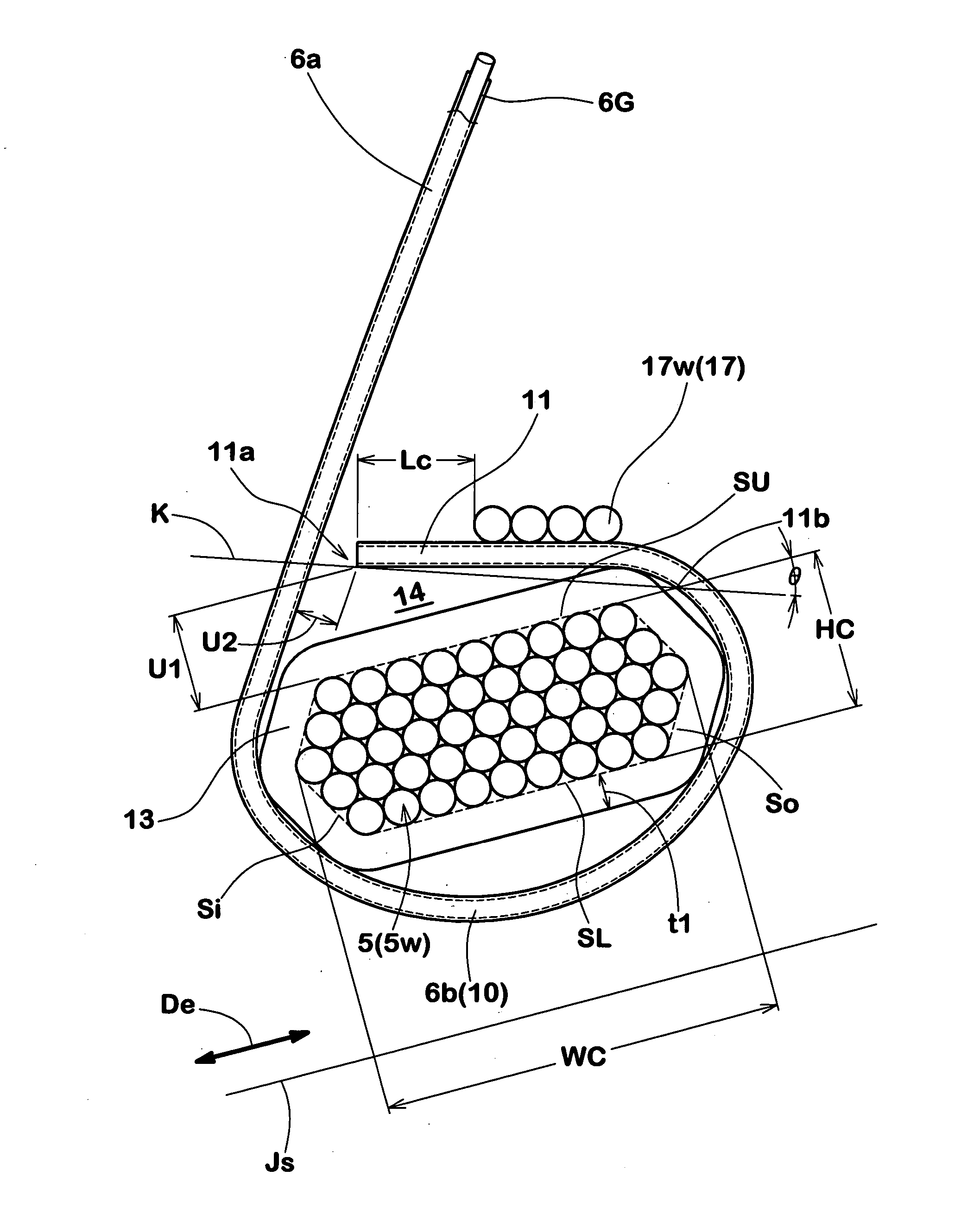
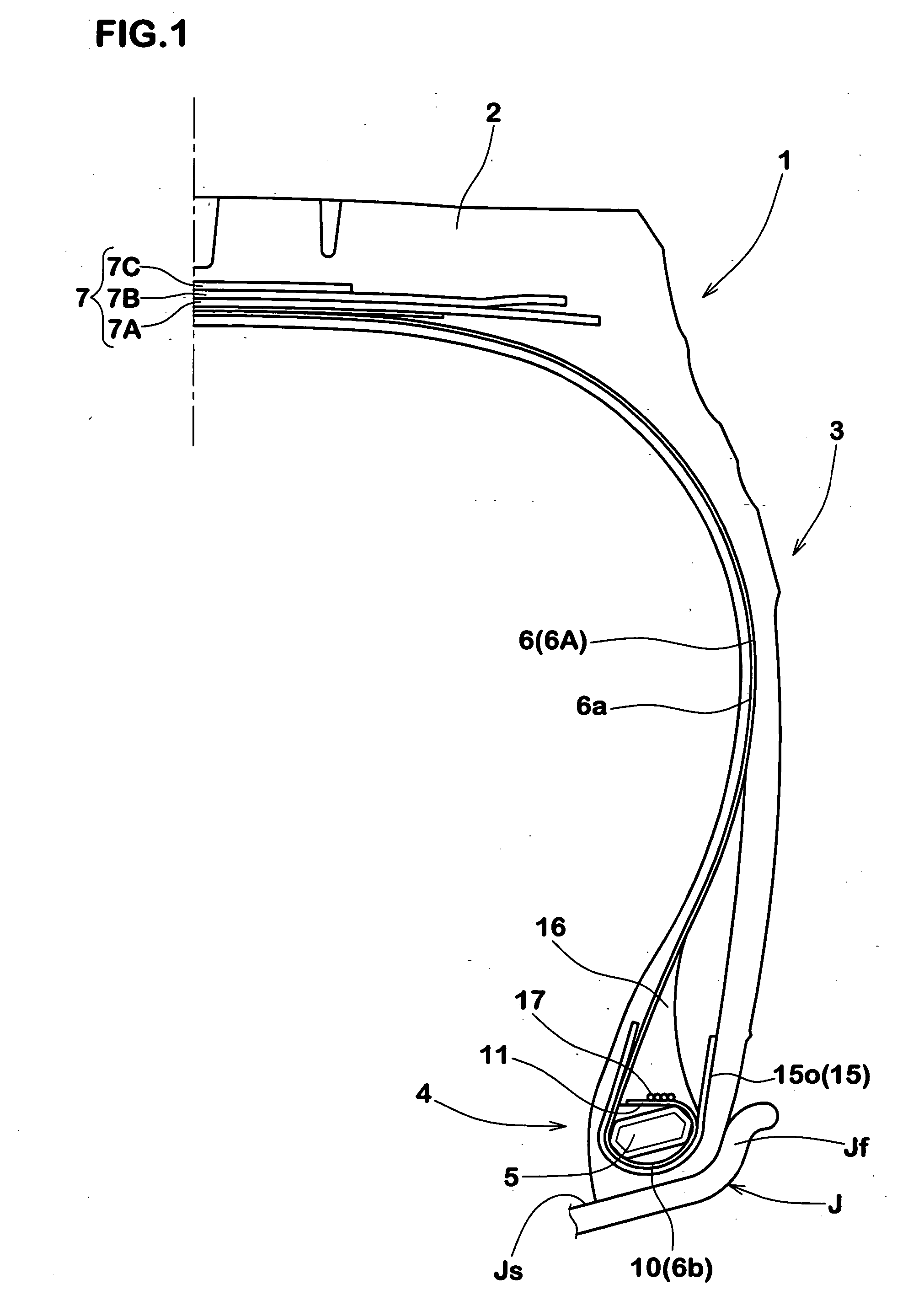
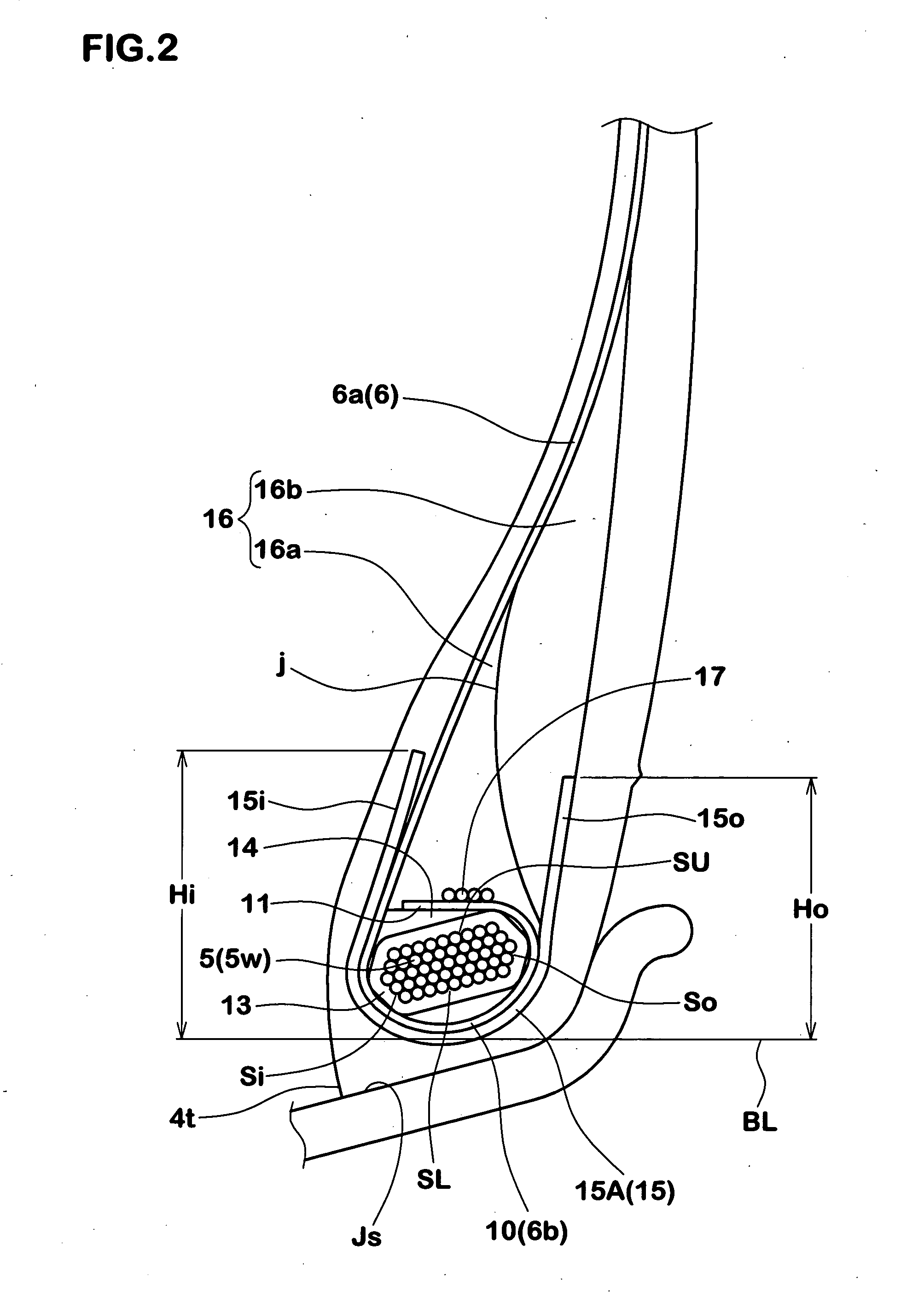
A pneumatic tire comprises a tread portion, a pair of sidewall portions, a pair of bead portions with a bead core therein, and a carcass ply extending between the bead portions through the tread portion and sidewall portions and wound around the bead core in each of the bead portions from the axially inside to the axially outside of the tire so as to form a pair of wound portions and a main portion therebetween, wherein the bead core has a cross sectional shape elongated in a direction substantially parallel to the bottom of the bead portion so that the width (WC) thereof measured in this direction is in a range of from 1.5 to 2.5 times the height (HC) thereof measured perpendicularly thereto, and the bead core is covered with a high modulus rubber layer having a complex elastic modulus E*1 of from 20 to 100 Mpa and a thickness t1 of from 0.5 to 3.0 mm.
Description
BACKGROUND OF THE INVENTION [0001] The present invention relates to a pneumatic tire, more particularly to a bead structure suitable for heavy duty tires such as truck / bus tires which is capable of improving the bead durability. [0002] In recent years, as a carcass securing structure suitable for heavy duty tires, a carcass ply (a1) of which edge portions (a2) are wound almost once around the bead cores (b) as shown in FIG. 5 has been proposed as disclosed in Japanese patent application publication No. JP-A-2005-162057 (also disclosed in family members US2005 / 0081976A1 and CN1605481A). [0003] This structure contributes to a remarkable tire weight reduction and also has advantages that bead failures such as cord loosening and ply separation which are liable to occur starting from the terminal end of the carcass ply can be prevented because the terminal end (a2e) of the wound portion (a2) is positioned in a relatively stable region near the bead core (b). [0004] On the other hand, as ...
Claims
Login to View More Application Information
Patent Timeline
 IPC IPC(8): B60C15/00
CPCB60C15/0027B60C15/04B60C15/06B60C2200/06Y10T152/10828B60C15/0607B60C2015/044Y10T152/10846B60C15/0635
InventorMARUOKA, KIYOTO
OwnerSUMITOMO RUBBER IND LTD