
Display device, drive device, and drive method

Inactive Publication Date: 2007-03-15
SEIKO EPSON CORP
View PDF2 Cites 28 Cited by
  • Summary
  • Abstract
  • Description
  • Claims
  • Application Information

AI Technical Summary

Benefits of technology

[0007] An object of the present invention is therefore to provide a display device that can avoid displaying inconsistent colors resulting from the electrophoretic characteristics of the display areas when the display is switched, and to provide a drive device and a drive method for driving this electrophoretic display panel.

Problems solved by technology

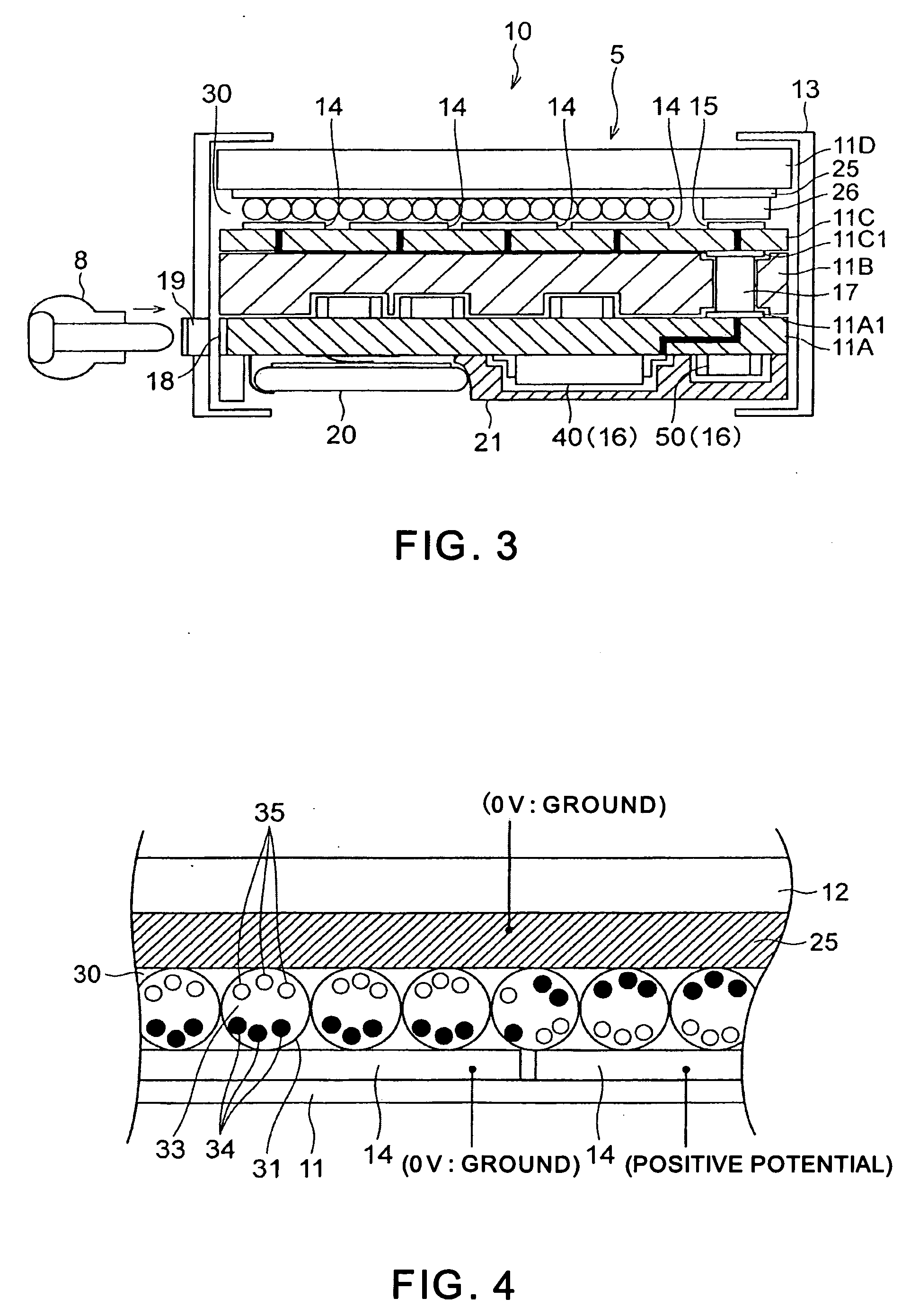
We discovered that if the display area to be switched to a different color is large when changing the content displayed on an electrophoretic display panel, the color will not change sufficiently even though the same drive voltage is applied, that is, the electrophoretic characteristics change according to the size of the display area in which the color is being changed.
As a result, if the display color is changed in different size areas, the achievable reflectivity will be lower in the larger area, and inconsistent colors result.

Method used


Image

  • Display device, drive device, and drive method
  • Display device, drive device, and drive method
  • Display device, drive device, and drive method

Examples


first embodiment

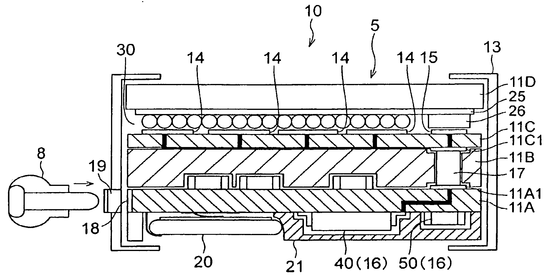
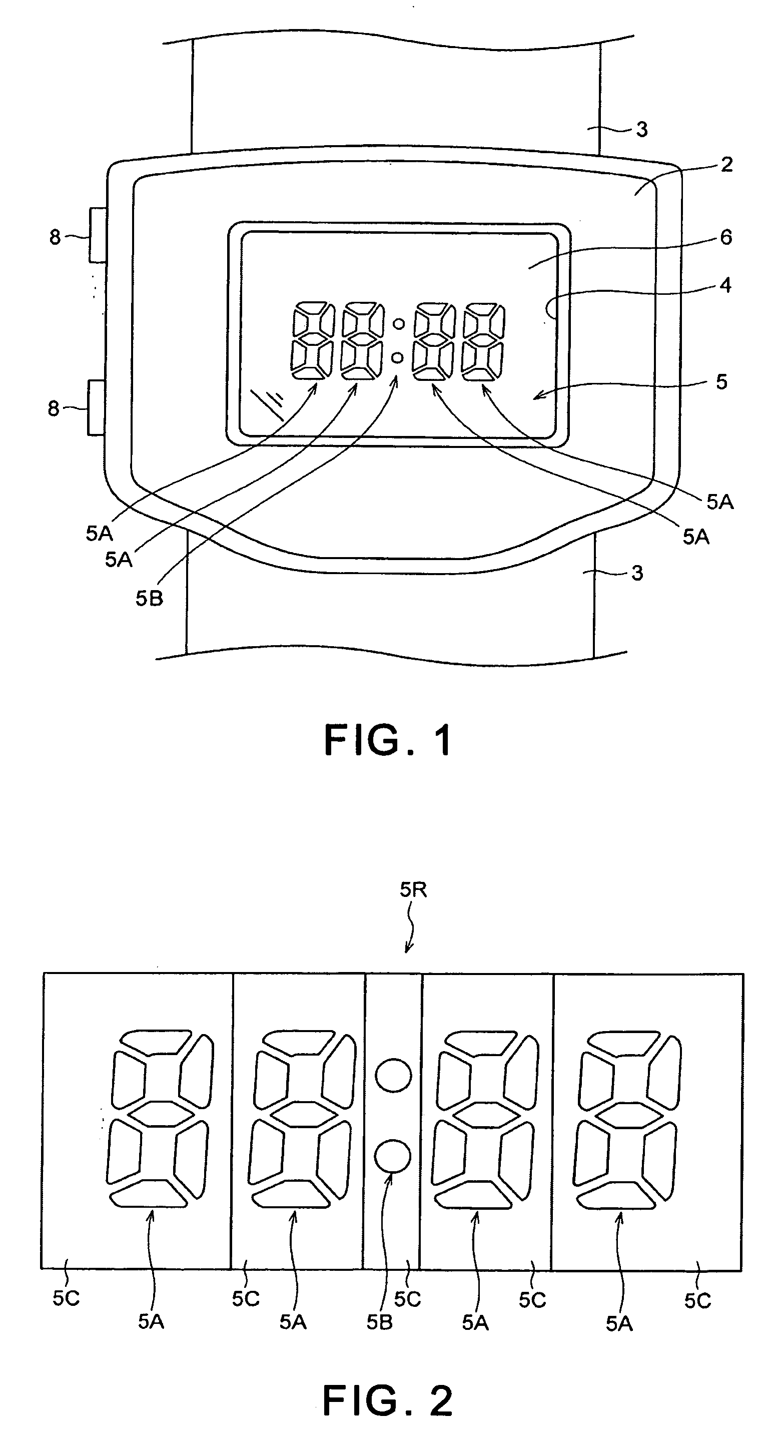
[0037]FIG. 1 shows the appearance of a wristwatch 1 according to this embodiment of the invention. As shown in the figure, the wristwatch 1 has a watch case 2, and a wrist band 3 that is attached to the watch case 2 and used to hold the wristwatch 1 on the user's wrist. A time display window 4 for displaying the time is formed in the front of the watch case 2 so that the display panel 5 that displays the time, for example, can be seen through the time display window 4. A crystal 6 made from transparent plastic or transparent glass, for example, is fit into the time display window 4, and the display panel 5 is protected by this crystal 6. Operating buttons 8 for setting the time, changing the operating mode, and performing other operations are also disposed to the watch case 2.

[0038] The display panel 5 is a segment display panel for displaying information using a plurality of segments. As shown in FIG. 2, the display area 5R of this display panel 5 comprises four segments (so-calle...

second embodiment

[0081] A wristwatch 1 according to a second embodiment of the invention is identical to the wristwatch 1 according to the first embodiment except that the pulse count of the drive signal COM when changing the display color is changed according to the size of the display area in which the display color is being changed. Like parts in this and the first embodiment are identified by like reference numerals, and further description thereof is omitted below.

[0082]FIG. 10 is a flow chart of a drawing process according to this second embodiment of the invention. In the example shown in FIG. 8 the current level of four segments 5X is black level 4 and two of these segments 5XW are changed to display white level 4. The target level of all four segments when this process starts is set to black level 4 (the same level as the current level).

[0083] When a segment update is triggered, the control circuit 57 updates the target level of the segments 5XW to be updated to the target white level 4 (...


PUM


Abstract

A display device comprising an electrophoretic display panel comprising two types of electrophoretic particles of different color and polarity between electrodes, and a drive unit for supplying a drive signal to apply a drive voltage between the electrodes to switch a display color of the electrophoretic display panel between the colors of the electrophoretic particles. The drive unit supplies a drive signal of which the drive power is changed according to the electrophoretic characteristics when the display color of the electrophoretic display panel is changed in order to change the display color of the electrophoretic display panel.

Description

BACKGROUND [0001] 1. Field of Technology [0002] The present invention relates to technology for avoiding uneven display of colors on an electrophoretic display panel. [0003] 2. Description of Related Art [0004] Display devices comprising an electrophoretic display panel that operate using electrophoresis, a phenomenon whereby charged particles dispersed in a fluid migrate when an electric field is applied, are known from the literature. This type of electrophoretic display panel has an electrophoretic layer filled with black and white electrophoretic particles, for example, disposed between electrodes. When a drive voltage with a positive or negative potential is applied between the electrodes, either the black or the white electrophoretic particles migrate to the display surface side of the electrophoretic layer so that the color displayed at the display surface is white or black (see, for example, Japanese Unexamined Patent Appl. Pub. S52-70791). Migration of the electrophoretic p...

Claims


Application Information

Patent Timeline
IPC IPC(8): G09G3/34
CPCG09G3/16G09G3/344G09G2340/16G09G2320/04G09G2320/0257
Inventor ISHII, JUNICHIRONAGASAKI, SHINTARO
Owner SEIKO EPSON CORP
Learn More