
Ink jet printing device and image forming apparatus

a printing device and printing device technology, applied in printing mechanisms, printing, spacing mechanisms, etc., can solve the problems of color inconsistency becoming conspicuous on the recording sheet p as a whole, deteriorating the quality of printed images, etc., to prevent the occurrence, high-quality printing, and high-quality printing

Inactive Publication Date: 2008-07-08
RICOH KK
View PDF15 Cites 4 Cited by
  • Summary
  • Abstract
  • Description
  • Claims
  • Application Information

AI Technical Summary

Benefits of technology

[0017]An object of the present invention is to provide an improved ink jet printing device and image forming apparatus in which the above-mentioned problems are eliminated.
[0018]Another object of the present invention is to provide an ink jet printing device which can prevent the occurrence of color inconsistency on the recording medium and attain high-quality printing by maintaining the impact sequence of the ink without being reversed in the case of printing at a high resolution higher than the resolution determined according to the array interval of the discharge nozzles of the head unit.
[0019]Another object of the present invention is to provide an image forming apparatus which can prevent the occurrence of color inconsistency on the recording medium and attain high-quality printing by maintaining the impact sequence of the ink without being reversed in the case of printing at a high resolution higher than the resolution determined according to the array interval of the discharge nozzles of the head unit.

Problems solved by technology

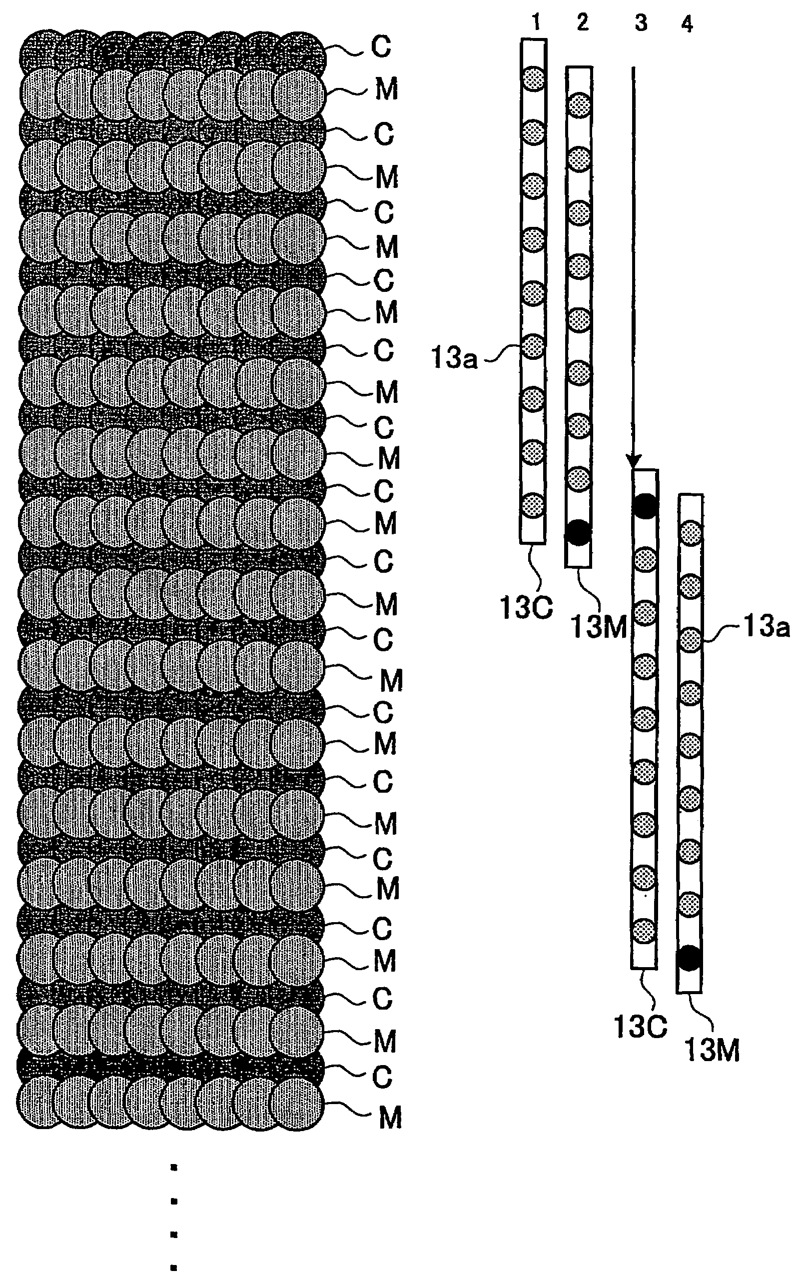
Namely, in the forward scanning, the ink drops overlap in order of Y, M, C, and B, but, in the backward scanning, the ink drops overlap in order of B, C, M, and Y. In this case, color inconsistency will occur in the printing result, and the quality of the printed image will be deteriorated.
The reversing of the impact sequence of the ink drops mentioned above arises at the transitional locations between the discharge nozzles 1a of the rear-end portion of the head unit 1 and the discharge nozzles 1a of the front-end portion of the head unit 1 when the recording sheet P is moved in the sub-scanning direction greatly and then the head unit 1 is moved to the non-printed region on the recording sheet P, and consequently the problem that color inconsistency becomes conspicuous on the recording sheet P as a whole will arise.

Method used


Image

  • Ink jet printing device and image forming apparatus
  • Ink jet printing device and image forming apparatus
  • Ink jet printing device and image forming apparatus

Examples


Embodiment Construction

[0049]A description will now be given of the preferred embodiments of the invention with reference to the accompanying drawings.

[0050]Referring to FIG. 1 through FIG. 7B, the ink jet printing device in the first preferred embodiment of the invention will be explained.

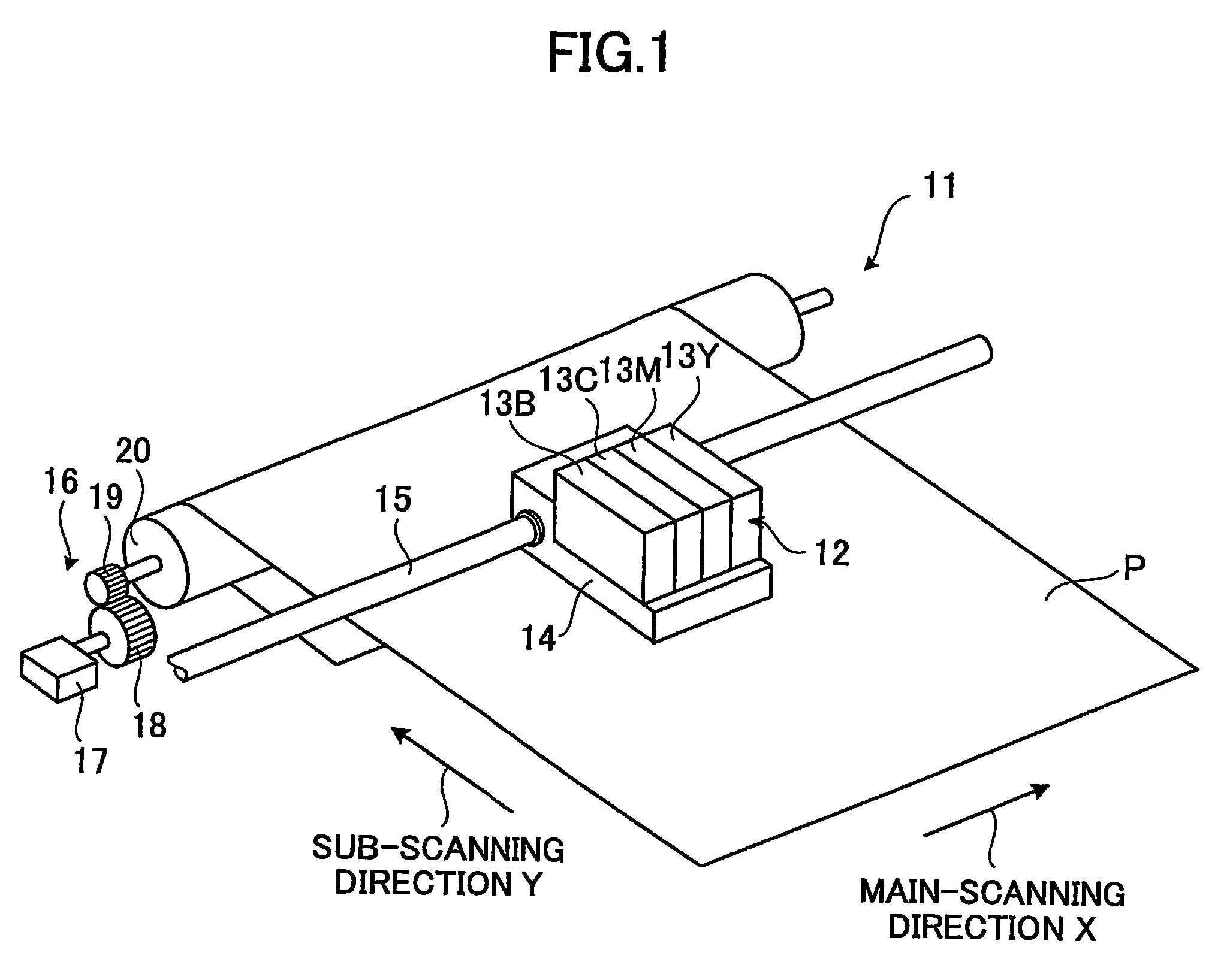
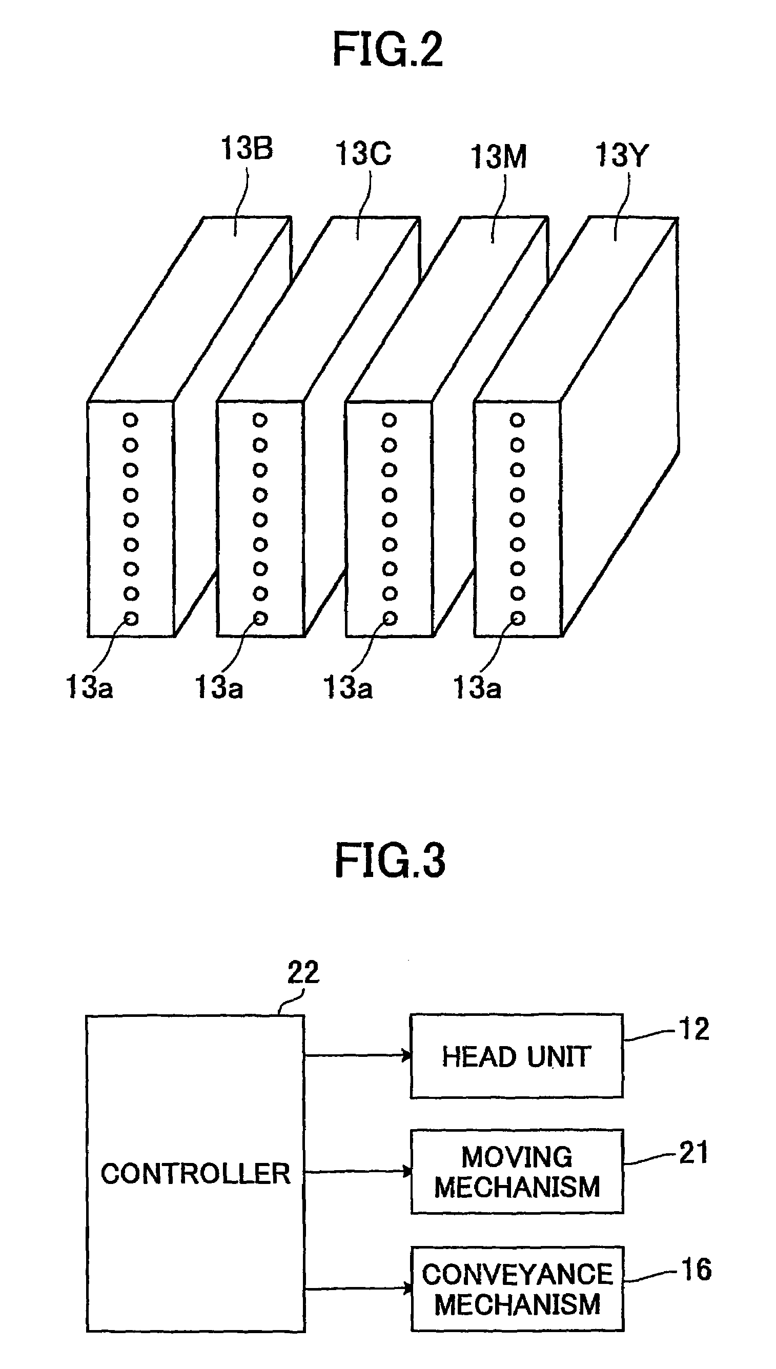
[0051]FIG. 1 and FIG. 2 show the composition of the ink jet printing device in the first preferred embodiment of the invention. The ink jet printing device 11 of FIG. 1 is provided in an image forming apparatus, such as a copier, a printer, a facsimile, a multi-function peripheral, etc. Since the image forming apparatus is well known in the art, the drawings showing the composition of the image forming apparatus will be omitted.

[0052]As shown in FIG. 1, the ink jet printing device 11 comprises the head unit 12. The head unit 12 includes the plurality of recording heads 13B, 13C, 13M, and 13Y which have the discharge nozzles 13a which discharge the ink drops of the black (B), the cyan (C), the magenta (M), and the yellow...


PUM


Abstract

An ink jet printing device comprises a head unit, a head-unit moving unit, a recording-medium moving unit, and a control unit controlling the head unit, the head-unit moving unit, and the recording-medium moving unit. The control unit is configured to carry out printing so that a rear-end portion of discharge nozzles in an array direction after printing of a printing region and a front-end portion of the discharge nozzles in the array direction before printing of a non-printed region overlap each other with respect to a sub-scanning direction, and invalid nozzles that do not discharge ink drops are determined from among arbitrary ones of overlapping discharge nozzles including a front-end portion and a rear-end portion in the array direction of the discharge nozzles.

Description

TECHNICAL FIELD[0001]The present invention generally relates to an ink jet printing device and an image forming apparatus, applicable to, for example, copiers, printers, facsimile, multi-function peripherals, etc., and more particularly to an ink jet printing device and an image forming apparatus configured to move the head unit in the main scanning direction multiple times repeatedly for the same printing region in accordance with the array interval of the discharge nozzles.BACKGROUND ART[0002]Conventionally, the ink jet printing device is used in the image forming apparatus, such as copier, printer, facsimile, multi-function peripheral, etc. In this ink jet printing device, the head unit includes a plurality of recording heads provided with a plurality of discharge nozzles arranged in the sub-scanning direction, and filled up with the inks of the different colors, and high-density and high-quality printing is carried out at high speed by discharging of ink drops from the discharge...

Claims


Application Information

Patent Timeline
Patent Type & Authority Patents(United States)
IPC IPC(8): B41J2/145B41J2/21B41J2/01B41J11/42
CPCB41J2/2132B41J19/147B41J11/42B41J2/2135B41J2/2139B41J2/2142
Inventor FUKUYASU, HIDEHITO
Owner RICOH KK
Learn More