Dot formation position misalignment adjustment performed using pixel-level information indicating dot non-formation

a technology of pixel-level information and dot formation, applied in the direction of printing, spacing mechanisms, printing mechanisms, etc., can solve the problems of reducing image quality, image quality deterioration, and the above-described conventional dot formation position misalignment adjustment method has various inherent limitations, so as to reduce the time required for printing

Inactive Publication Date: 2006-01-10
SEIKO EPSON CORP
View PDF22 Cites 19 Cited by
  • Summary
  • Abstract
  • Description
  • Claims
  • Application Information

AI Technical Summary

Benefits of technology

[0041]It is preferred that the head be driven along both the forward and reverse passes of main scanning. In this arrangement, the time required for printing may be reduced. The head may also be driven either the forward or reverse scanning passes. In this arrangement, the problem of dot formation position misalignment attributable to the different main scanning directions can be avoided.
[0042]Where the plurality of nozzles classified into a plurality of nozzle rows that extend in the sub-scanning direction and that are aligned in the main scanning direction with a prescribed interval therebetween, the delay data may be used. The delay data indicates an amount of delay needed to correct for a difference in times that nozzles arrive at a particular pixel during main scanning in accordance with a design distance in the main scanning direction between the plurality of nozzles. In this case, it is preferred that the following steps occur. First, the delay data are readjusted, so that the dot formation position misalignment amount may be corrected. Then using the readjusted delay data as the adjustment pixel value data, serial data is generated. The serial data includes the readjusted delay data and the image pixel value data that follows the readjusted delay data, for each nozzle during each main scanning session. Dots are then formed based on the serial data. In this arrangement, the delay data to compensate for the interval between the nozzles in the main scanning direction is effectively used to correct dot formation position misalignment.

Problems solved by technology

If the positions at which the dots of each color are formed are misaligned, it would cause a problem of reduced image quality.
This problem of image quality deterioration due to dot formation misalignment occurs in both uni-directional recording and bi-directional recording.
However, the above-described conventional dot position misalignment adjustment method has various inherent limitations.
For example, because the drive signal timing can be changed only for the entire print head in a typical printer, dot position misalignment adjustment is limited to what can be achieved by the timing change.

Method used


Image

  • Dot formation position misalignment adjustment performed using pixel-level information indicating dot non-formation
  • Dot formation position misalignment adjustment performed using pixel-level information indicating dot non-formation
  • Dot formation position misalignment adjustment performed using pixel-level information indicating dot non-formation

Examples


first embodiment

(4) First Embodiment

(4-1) Print Data Generation

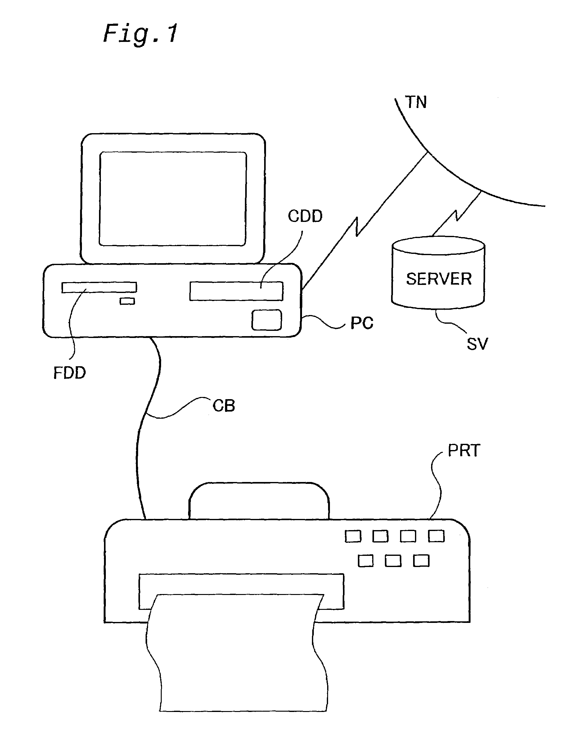
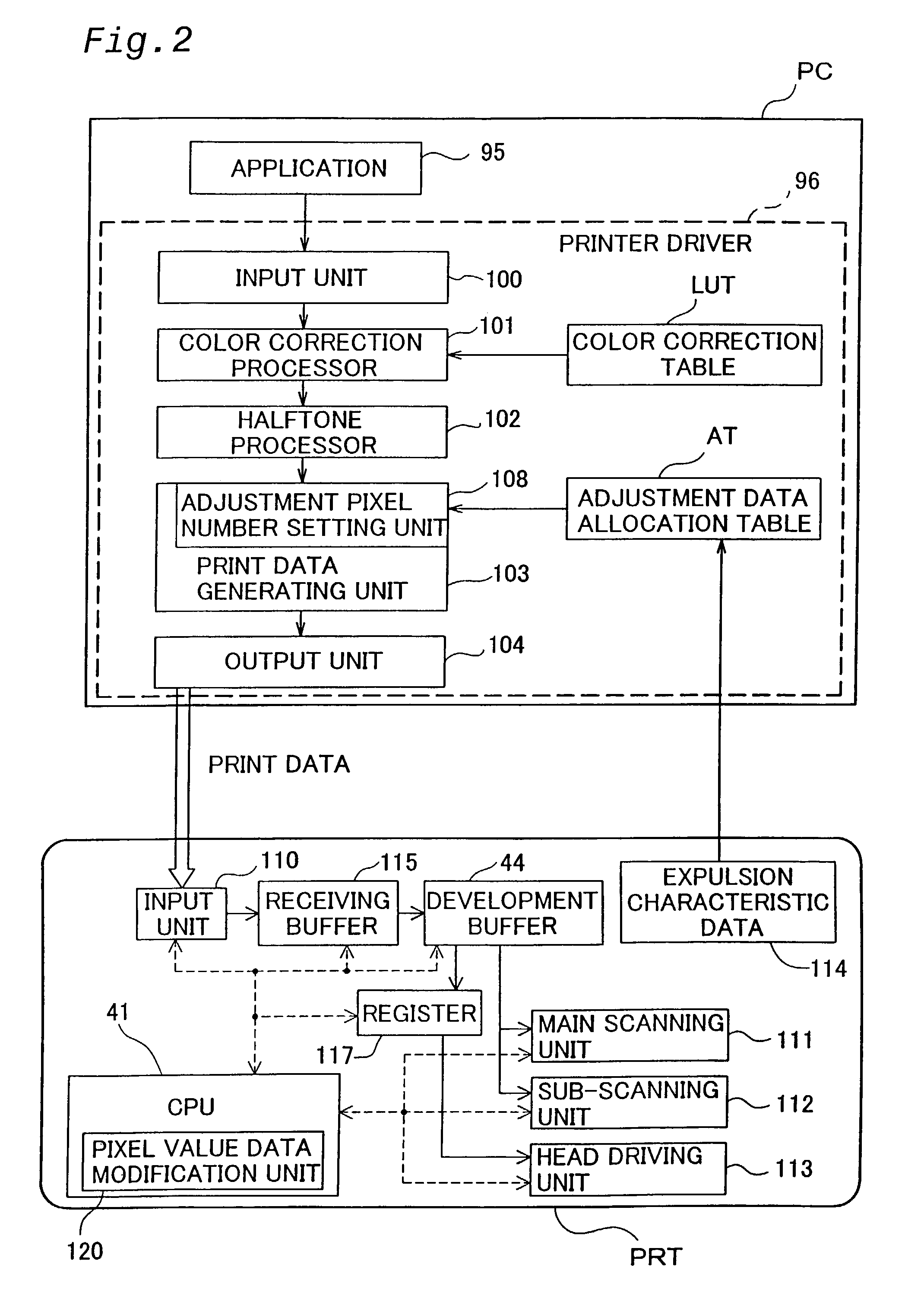
[0154]The configuration of the hardware in this embodiment is as described above (see FIGS. 1 through 4). In this embodiment, correction of dot position misalignment is carried out during bi-directional printing, i.e., printing in which printing is performed while the carriage is moving in both the forward and reverse directions.

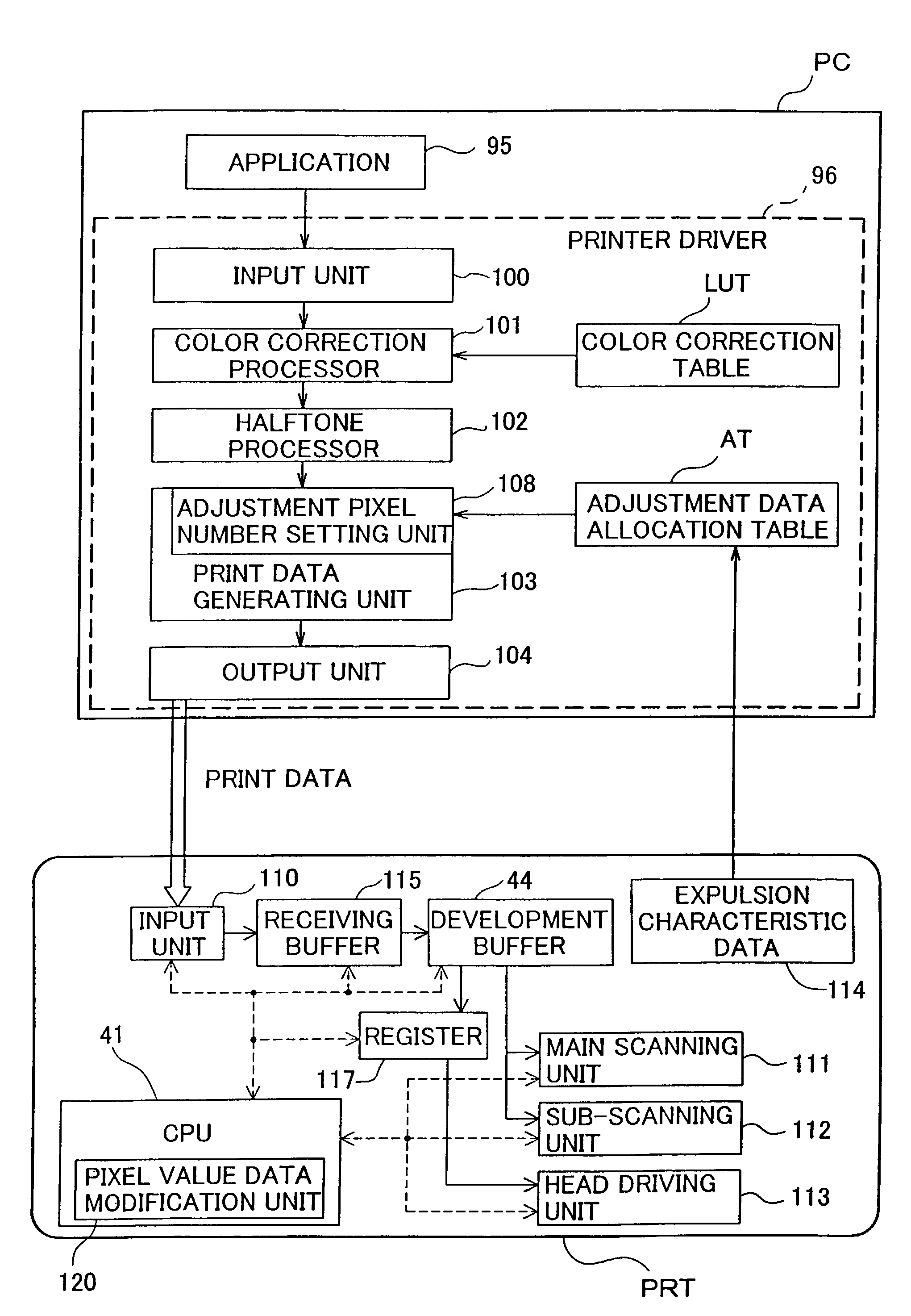
[0155]FIG. 18 is a flow chart of the print data generating process routine for this embodiment. This process is executed by the CPU of the computer PC. When this process is begun, the input unit 100, the color correction processor 101 and the halftone processor 102 (see FIG. 2) carry out image data input, color correction processing and halftoning, respectively (steps S10, S20, S30). These processes are the same as those shown in FIG. 7.

[0156]Next, the print data generating unit 103 determines the subject nozzles and the formation direction (step S35). As explained previously (see FIG. 17), where the feed amount...

second embodiment

(5) Second Embodiment

[0182]FIG. 27 is a drawing showing the configuration of the function blocks of a second embodiment. In the second embodiment, the printer driver 96 contains function blocks of, in addition to the input unit 100 and the output unit 104, a normal printing module 105, a test pattern printing module 106, and a test pattern memory unit 107. The configuration of the printer PRT is the same as that described above with reference to FIG. 2.

[0183]The normal printing module 105 is a comprehensive function block representing the color correction processor 101, the color correction table LUT, the halftone processor 102, the print data generating unit 103, and the adjustment data allocation table AT. The test pattern printing module 106 prints test patterns based on test patterns stored beforehand in the test pattern memory unit 107. Therefore, the second embodiment effectively adds the new function of printing test patterns to the functions included in the above explanation...

third embodiment

(6) Third Embodiment

[0202]FIG. 32 is a drawing showing the function blocks of a printing apparatus. The third embodiment differs from the first embodiment with regard to the head driving unit 113a in the printer PRT and the print data generating unit 103a in the computer PC. It is identical to the first embodiment regarding other components. The head driving unit 113a in the printer PRT has a drive signal generating unit 116. While explanation is omitted in connection with the first embodiment, the head driving unit 113 of the first embodiment also has a drive signal generating unit. However, the drive signal generating unit 116 of the third embodiment is characterized in that it generates drive signals to drive each nozzle based on four base drive signals explained below. The print data generating unit 103a has a pass splitting unit 109 that determines which of the base drive signals will be used to record the image pixels in the raster line.

[0203]While explanation is omitted in co...


PUM


Abstract

While performing main scanning in which a head having a plurality of nozzles that eject ink is moved in prescribed forward and reverse main scanning directions relative to a print medium, print images are printed on the print medium by forming dots in each pixel aligned in the main scanning direction in accordance with print data. The dot formation position misalignment amount for each nozzle is corrected using image pixel value data indicating the existence of image pixels comprising images and adjustment pixel value data indicating the existence of adjustment pixels in which dots are not formed.

Description

TECHNICAL FIELD[0001]The present invention pertains to a printing apparatus and printing method for printing images through formation of monochrome or multi-color dots on a recording medium during main scanning.BACKGROUND ART[0002]An inkjet printer is used as a device for outputing images processed by a computer or images captured by a digital camera. An inkjet printer forms dots by ejection of ink of various colors such as cyan, magenta, yellow and black, for example. Dots of each color are typically ejected from a print head while the print head is moving in a main scanning direction. If the positions at which the dots of each color are formed are misaligned, it would cause a problem of reduced image quality.[0003]This problem of image quality deterioration due to dot formation misalignment occurs in both uni-directional recording and bi-directional recording. Here, uni-directional recording refers to a recording method in which, where the print head moves back and forth along the...

Claims


Application Information

Patent Timeline
Patent Type & Authority Patents(United States)
IPC IPC(8): B41J29/393B41J29/38B41J2/21B41J19/14
CPCB41J2/2132B41J19/145B41J2/2135
Inventor SHIMADA, KAZUMICHIHAYASHI, TOSHIHIROKANAYA, MUNEHIDEOTSUKI, KOICHI
Owner SEIKO EPSON CORP
Why Eureka
Try Eureka