

Both-side recording apparatus
- Summary
- Abstract
- Description
- Claims
- Application Information
AI Technical Summary
Benefits of technology
Problems solved by technology
Method used
Image

Examples
Embodiment Construction
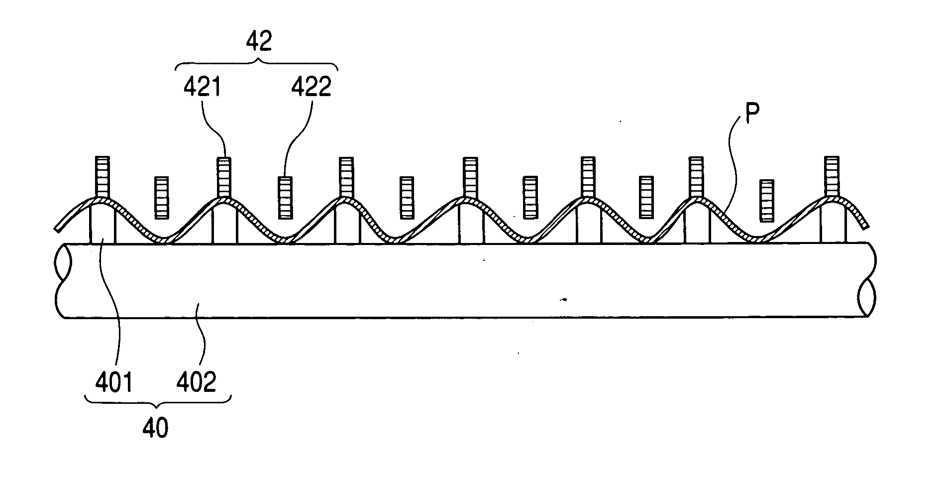
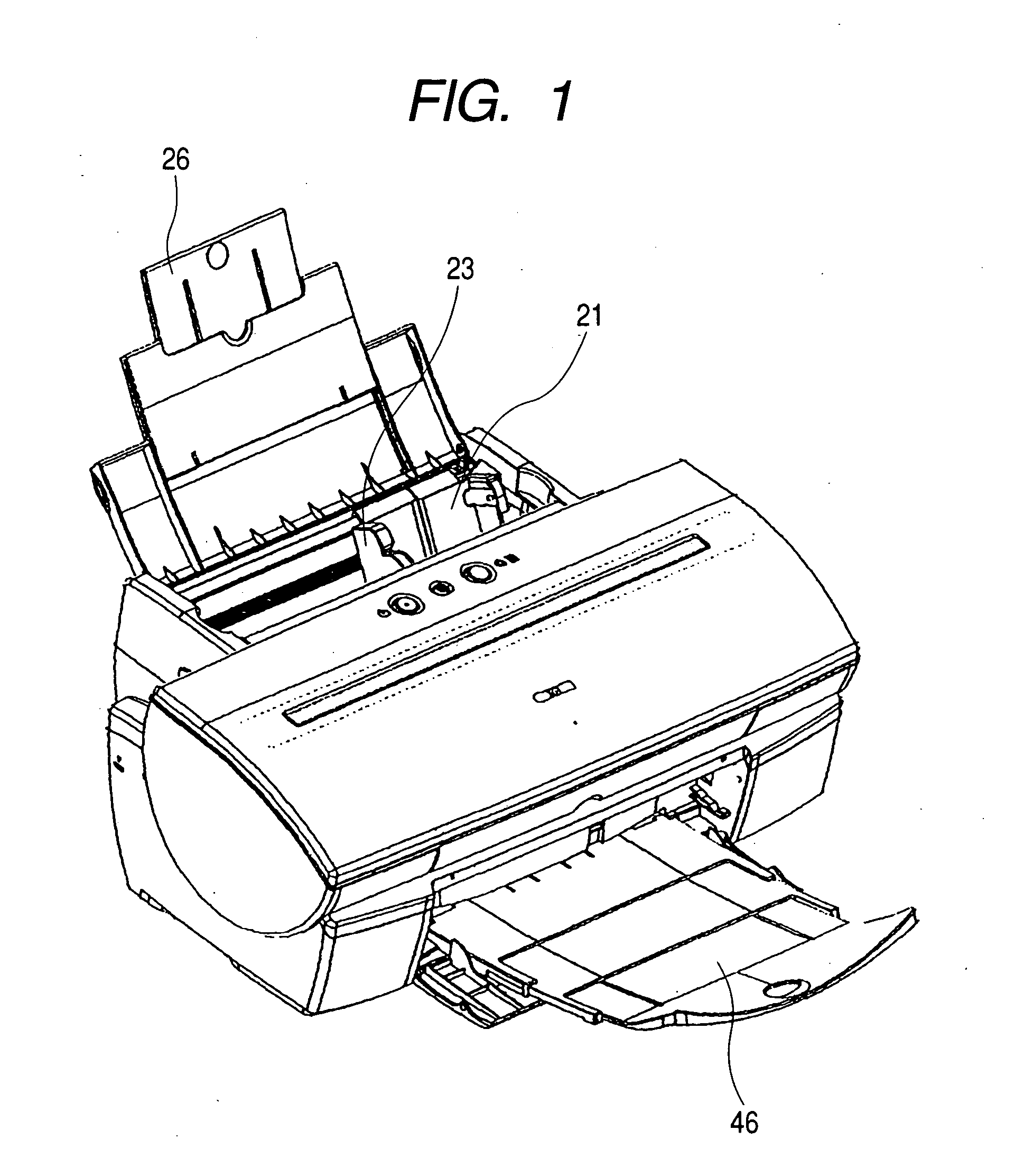
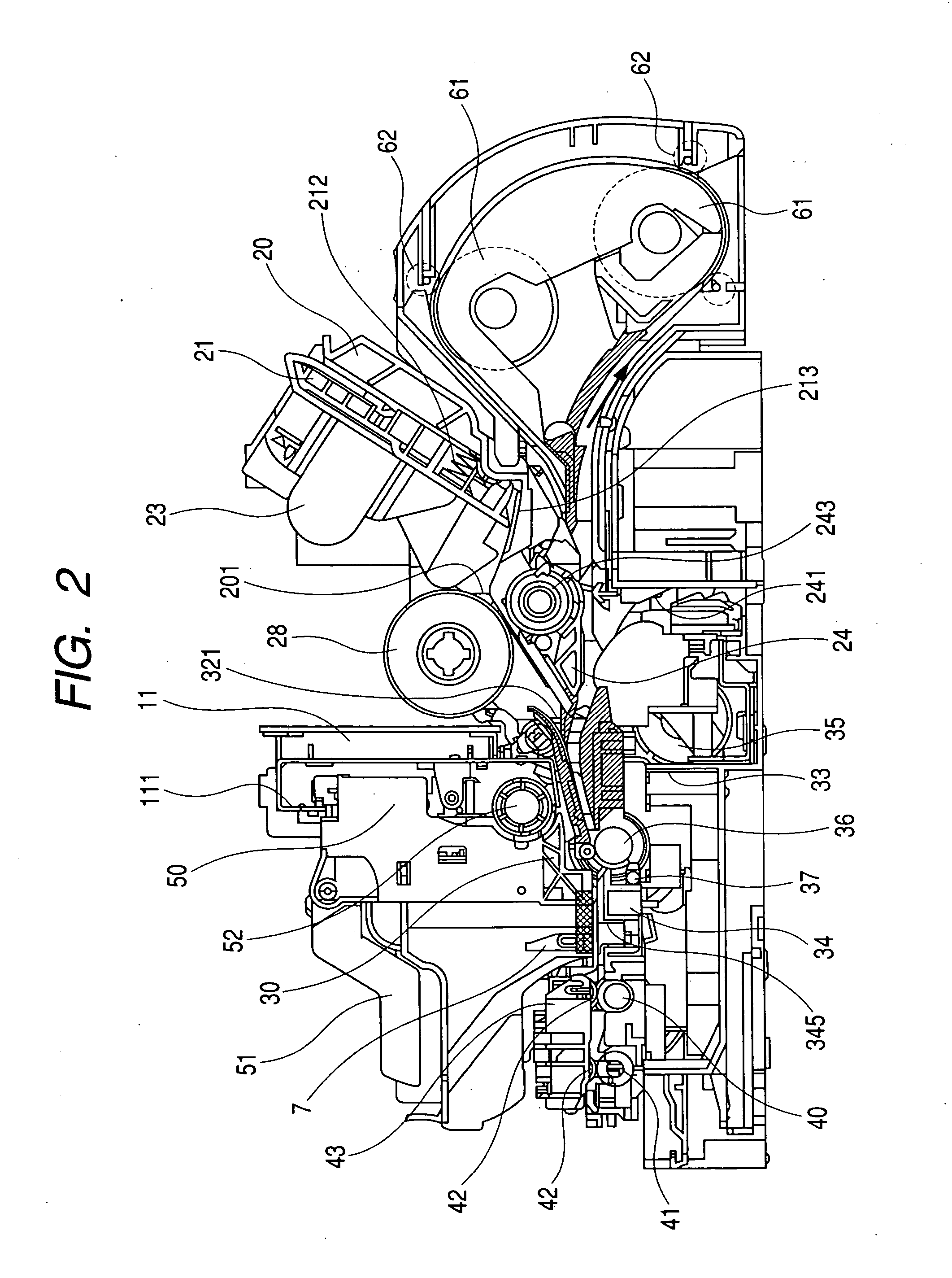
[0033] A first embodiment of the both-side recording apparatus of the present invention will hereinafter be described with reference to FIGS. 1 to 9A and 9B. FIG. 1 is a perspective view of the both-side recording apparatus according to the first embodiment of the present invention. FIG. 2 is a cross-sectional view of the both-side recording apparatus according to the first embodiment of the present invention. FIG. 3 is an enlarged cross-sectional view of a sheet expelling portion and a carriage portion. FIG. 4 is a typical view of the sheet expelling portion as it is seen from the conveying direction of a recording medium. FIG. 5 is a flow chart showing a series of steps of effecting recording on the recording medium P. FIGS. 6A and 6B to 9A and 9B are typical views showing the states of the recording medium P at the main steps shown in FIG. 5. FIG. 14 is a control block diagram of the both-side recording apparatus.
[0034] The basic construction of the both-side recording apparatus...
PUM
 Abstract
Description
Claims
Application Information