Label producing apparatus and label producing method

a label producing and label technology, applied in the direction of printing, typewriters, other printing apparatus, etc., can solve the problems of decreasing the quality of printed labels and the detection accuracy of errors, and achieve the effect of reducing the fluctuation width of detected voltage, high accuracy, and reliably detecting positioning marks

Active Publication Date: 2011-09-08
BROTHER KOGYO KK
View PDF5 Cites 18 Cited by
  • Summary
  • Abstract
  • Description
  • Claims
  • Application Information

AI Technical Summary

Benefits of technology

[0013]Note that external light may enter the housing from the discharging exit of the housing depending on the format of use of the user, such as indoor or outdoor use in a bright location, for example, affecting detection of the positioning mark by the above-described optical sensor. According to prior art, while the positioning mark is detected by a significant decrease in the received amount of light of the light receiving device and a significant change in the detected voltage based on the nature of the light absorbing characteristics of the positioning mark as described above, when the above-described external light enters the apparatus, the changing behavior of the received amount of light of the light receiving device caused by the positioning mark is alleviated by the external light. That is, the decrease in the amount of change of the detected voltage previously described decreases the fluctuation width of the detected voltage, possibly resulting in the received amount of light failing to arrive at the initial threshold value even when light is projected on the positioning mark, making positioning mark detection difficult.
[0014]According to the aspect of the present disclosure, the threshold value correction portion corrects the initial threshold value taking into consideration the effect of the above-described external light, based on the correction instruction signal. That is, the corrected threshold value is calculated at a predetermined time when the light projecting device is in an off state and external light can enter from the discharging exit. As a result, it is possible to set a new corrected threshold value in accordance with the fluctuation width at the time external light that presumably has a narrower fluctuation width enters. With this arrangement, it is possible to make the voltage value corresponding to the received amount of light when light is projected on the positioning mark lower (or higher) than the corrected threshold value and thus reliably detect the positioning mark.
[0015]Therefore, regardless of the behavior of the detected voltage caused by the above-described entry of external light, the positioning mark can be detected with high accuracy. As a result, feeding control and printing control can be performed with high accuracy regardless of the format of use of the user, making it possible to produce a high-quality printed label without variance in the feeding distance or shift in the printing position.

Problems solved by technology

With such an arrangement, a decrease in detection accuracy of the tape position with respect to the tape feeding direction occurs, resulting in variance of the feeding distance and a shift in the printing position, possibly decreasing the quality of the printed label.

Method used


Image

  • Label producing apparatus and label producing method
  • Label producing apparatus and label producing method
  • Label producing apparatus and label producing method

Examples


Embodiment Construction

tion of a mark sensor.

[0030]FIG. 15 is a time chart showing the change in the detected voltage value before and after detection of the black mark when the exemplary modification of the mark sensor is used.

[0031]FIG. 16 is a time chart showing the change in the detected voltage value V before and after the mark sensor detects the front end of the tag tape, etc., in an exemplary modification in which correction is performed after detection of the passing of the front end of the tag tape.

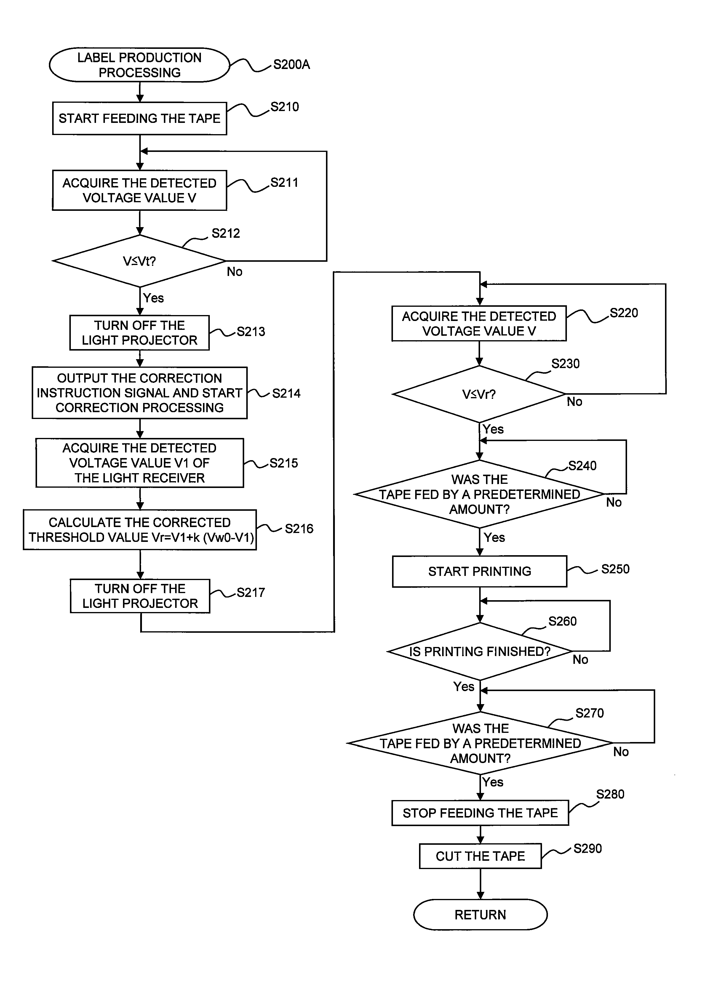
[0032]FIG. 17 is a flowchart illustrating the control contents executed by the CPU of the tag label producing apparatus.

[0033]FIG. 18 is a flowchart which shows the detailed procedure of step S200A.

DETAILED DESCRIPTION OF THE PREFERRED EMBODIMENTS

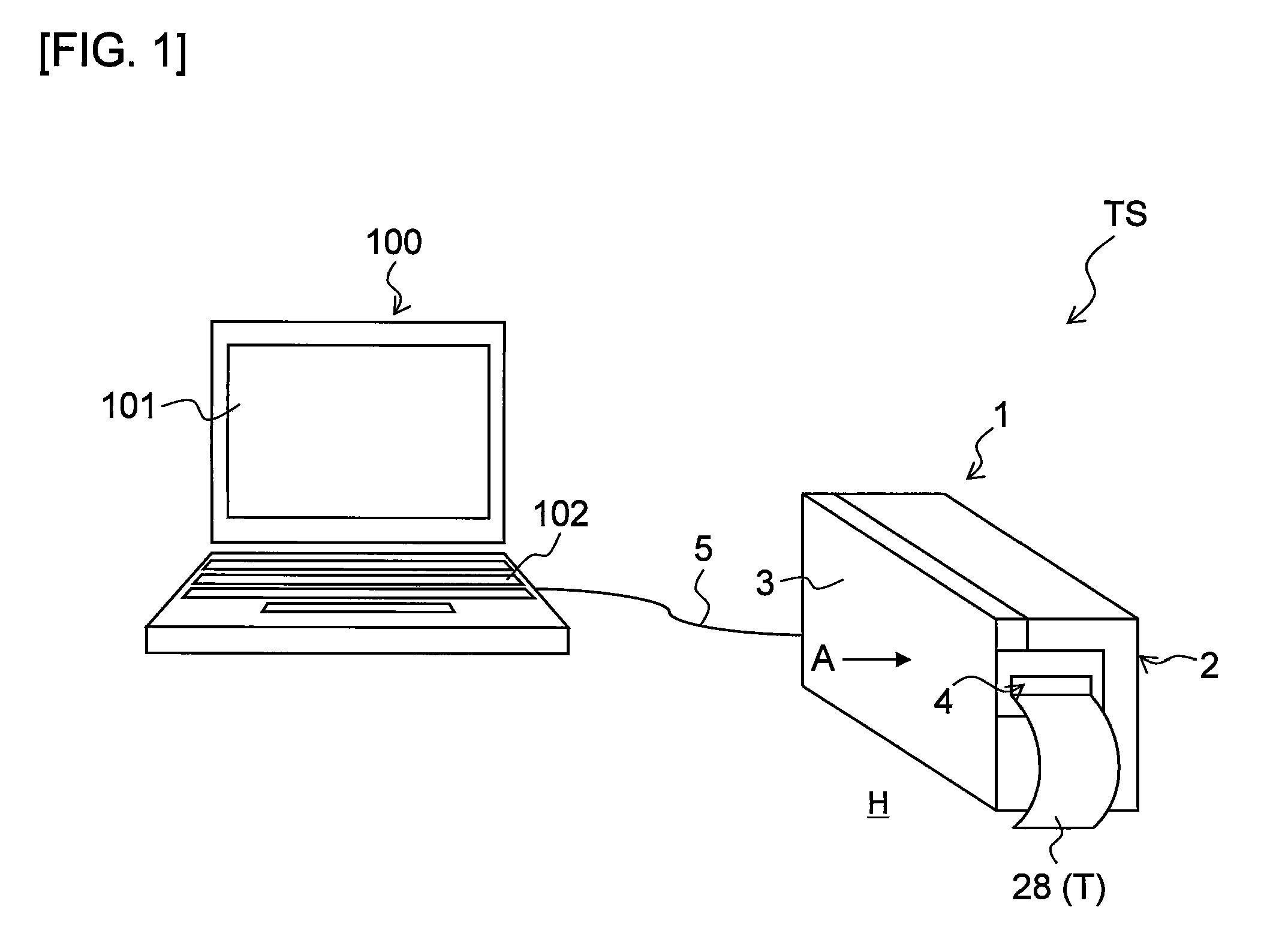
[0034]The following describes an embodiment of the present disclosure with reference to accompanying drawings. The present embodiment is of a case where the present disclosure is applied to an RFID label producing system.

[0035]The overall configuration of a ta...


PUM


Abstract

This disclosure discloses a label producing apparatus comprising: a housing; a feeding device that feeds a label tape; a printing device that prints desired print; an optical sensor comprising a light projecting device and a light receiving device capable of outputting a detected voltage value; a light-on control portion that controls said optical sensor so that said light projecting device is turned on; an initial value storage device that stores a predetermined initial threshold value; a threshold value correction portion that calculates a corrected threshold value using said initial threshold value; a mark detecting portion that detects a positioning mark by an arrival of said detected voltage value at said corrected threshold value after calculation of said corrected threshold value; a feeding control portion that controls said feeding device; and a print control portion that controls a print operation of said printing device.

Description

CROSS-REFERENCE TO RELATED APPLICATION[0001]The present application claims priority from Japanese Patent Application No. 2010-47523, which was filed on Mar. 4, 2010, the disclosure of which is incorporated herein by reference in its entirety.BACKGROUND[0002]1. Field[0003]The present disclosure relates to a printed label producing apparatus and a label producing method for printing print on a label tape and creating a printed label.[0004]2. Description of the Related Art[0005]In prior art, there has been proposed a label producing apparatus that produces a printed label by storing a tape that serves as a print-receiving material in a roll shape inside a tape cartridge, printing desired print on the tape as the tape is fed out from the roll, and cutting the tape with print with a cutter.[0006]For such a label producing apparatus, a technique has been proposed in which a light-absorbing black mark is printed in a predetermined position in the feeding direction of the tape in advance, a...

Claims


Application Information

Patent Timeline
Patent Type & Authority Applications(United States)
IPC IPC(8): B41J11/42
CPCB41J11/46B41J3/4075
Inventor IMAMURA, YUSUKEIRIYAMA, YASUHIRO
Owner BROTHER KOGYO KK
Why Eureka
Try Eureka