Liquid Container, Liquid Consuming Apparatus, Liquid Supply System and Liquid Container Unit

a liquid container and consuming apparatus technology, applied in printing and other directions, can solve the problems of ink leakage from the recording head, inability to supply ink to the recording head, and uneven density of the ink used in such an ink jet recording apparatus,

Inactive Publication Date: 2014-02-13
SEIKO EPSON CORP
View PDF1 Cites 87 Cited by
  • Summary
  • Abstract
  • Description
  • Claims
  • Application Information

AI Technical Summary

Benefits of technology

[0450](1) It is possible to inject ink into the ink chamber 50 through the injection port 52 on the ink tank 43. In addition, since the tank unit 27 is fixedly attached to the apparatus main body 13, it is possible to decrease the possibility that the tank unit 27 may be detached from the apparatus main body 13 when a user carries the recording apparatus 12. Therefore, the recording apparatus 12, including the tank unit 27 into which ink can be injected, can have improved portability.
[0451](2) Since the cover 44 is disposed to be slidable, it is possible to reduce the spatial area required for displacing the cover 44 compared to, for example, a cover that is displaced between the hiding position and the non-hiding position by being pivoted about an axis. Therefore, even when the recording apparatus 12 is installed in a narrow space, it is possible to open and close the cover 44.
[0452](3) When injecting the ink into the ink chamber 50 through the injection port 52, it is possible to place the closing member 58 on the placement portion 75. Therefore, even when the ink clings to the closing member 58, it is possible to decrease the possibility that the ink may adhere to a location other than the placement portion 75.
[0453](4) Since the injection port 52 is formed on the cylinder portion 53 protruding outward from the ink chamber 50, it is possible to decrease a possibility that, when injecting ink into the ink chamber 50, members located around the cylinder portion 53 contact the container for injecting ink (for example, a large size ink container), and interferes with ink injection. Furthermore, since the cylinder portion 53 protrudes toward the upward right direction non-orthogonal to the vertical direction Z, a user is able to easily check the state of the ink injection operation.
[0454](5) The convex barrier portion 55, which is disposed on the injection port forming surface 54 along which leaked ink will flow, can block ink that leaks from the injection port 52.
[0455](6) By suppressing the fluctuation range of the liquid level 51 with respect to the amount of the ink that flows from the ink chamber 50, it is possible to decrease change in pressure applied to the ink to supply it the liquid ejecting head 32. Therefore, it is possible to stably supply ink contained in the ink chamber 50 to the liquid ejecting head 32.

Problems solved by technology

In addition, the ink used for such an ink jet recording apparatus, like the pigmented ink for example, may have a certain unevenness in the density with the lapse of time.
That is, for example, if the recording head is located at a position considerably lower than the liquid level of the ink, there is a possibility that the ink may leak out from the recording head.
On the other hand, if the recording head is located at a position considerably higher than the liquid level of the ink, there is a possibility that the ink cannot be supplied to the recording head.
That is, the liquid consuming apparatus in the related art has a first problem in that it is difficult to stably supply the liquid to the liquid consuming unit side.
In addition, as similar to the ink jet recording apparatus disclosed in JP-A-2012-71585, the ink tank to which the ink can be injected has a second problem in that the ink is likely to leak out from the injection port when injecting the ink.
The tank case in the related art is configured to combine a plurality of members, whereby causing a third problem that the assembling needs labor hours.
In the ink jet recording apparatus disclosed in JP-A-2012-61624, in a case where the tank unit is mounted to be attachable and detachable with respect to the recording apparatus main body, there is a possibility that the tank unit may slip out of the recording apparatus when carrying the recording apparatus.
Therefore, it is necessary for a user to carry the recording apparatus while holding the tank unit or taking care of the slip, whereby causing a fourth problem of poor portability.
Therefore, if the lines are displayed so as to extend long in the horizontal direction of the check window, the positions of the liquid level of the ink with respect to the lines, particularly in both end positions of the line, are caused to differ from each other, whereby causing a fifth problem that it is difficult to determine the amount of the contained ink.
Therefore, there is a sixth problem in that it is difficult to inject the ink through the injection port.
Therefore, when transporting the ink jet recording apparatus in which the usable ink is contained in the ink tank, for example, when the ink tank is inverted, there is a possibility that the ink may leak out from the ink tank through the air opening port to the outside, whereby causing a seventh problem.
Furthermore, if the contained ink amount is increased, the required time is prolonged until the ink is used completely, whereby increasing unevenness in the density of the ink.
However, the ink is unlikely to flow in a portion horizontally far away from the ink outlet port in the ink containing chamber.
Therefore, there is an eighth problem in that the unevenness in the density of the ink cannot be sufficiently eliminated only by shaking the ink which has passed through different positions in the direction of gravity.
Then, if the outlet port is disposed at a first end side in a direction following the horizontal direction in the bottom portion of the ink chamber, it is not possible to cause the ink accumulated at the bottom surface side which is lowered by being tilted to flow out, when the ink jet recording apparatus is tilted and placed such that the first end side is located higher.
In particular, if the outlet port is disposed in the vicinity of the end portion of the ink chamber in the longitudinal direction, a large amount of the ink remains without flowing out when the ink chamber is tilted.
For example, in a case of the flow channel extending in the vertical direction, if the liquid is injected through the liquid injection port which is non-orthogonal to the vertical direction, there is a possibility that the injected liquid may be bumped against the wall of the flow channel and the rebounding may cause the surrounding to be contaminated.

Method used


Image

  • Liquid Container, Liquid Consuming Apparatus, Liquid Supply System and Liquid Container Unit
  • Liquid Container, Liquid Consuming Apparatus, Liquid Supply System and Liquid Container Unit
  • Liquid Container, Liquid Consuming Apparatus, Liquid Supply System and Liquid Container Unit

Examples


first embodiment

[0362]Hereinafter, a first embodiment of a recording apparatus which is an example of a liquid consuming apparatus will be described with reference to the accompanying drawings.

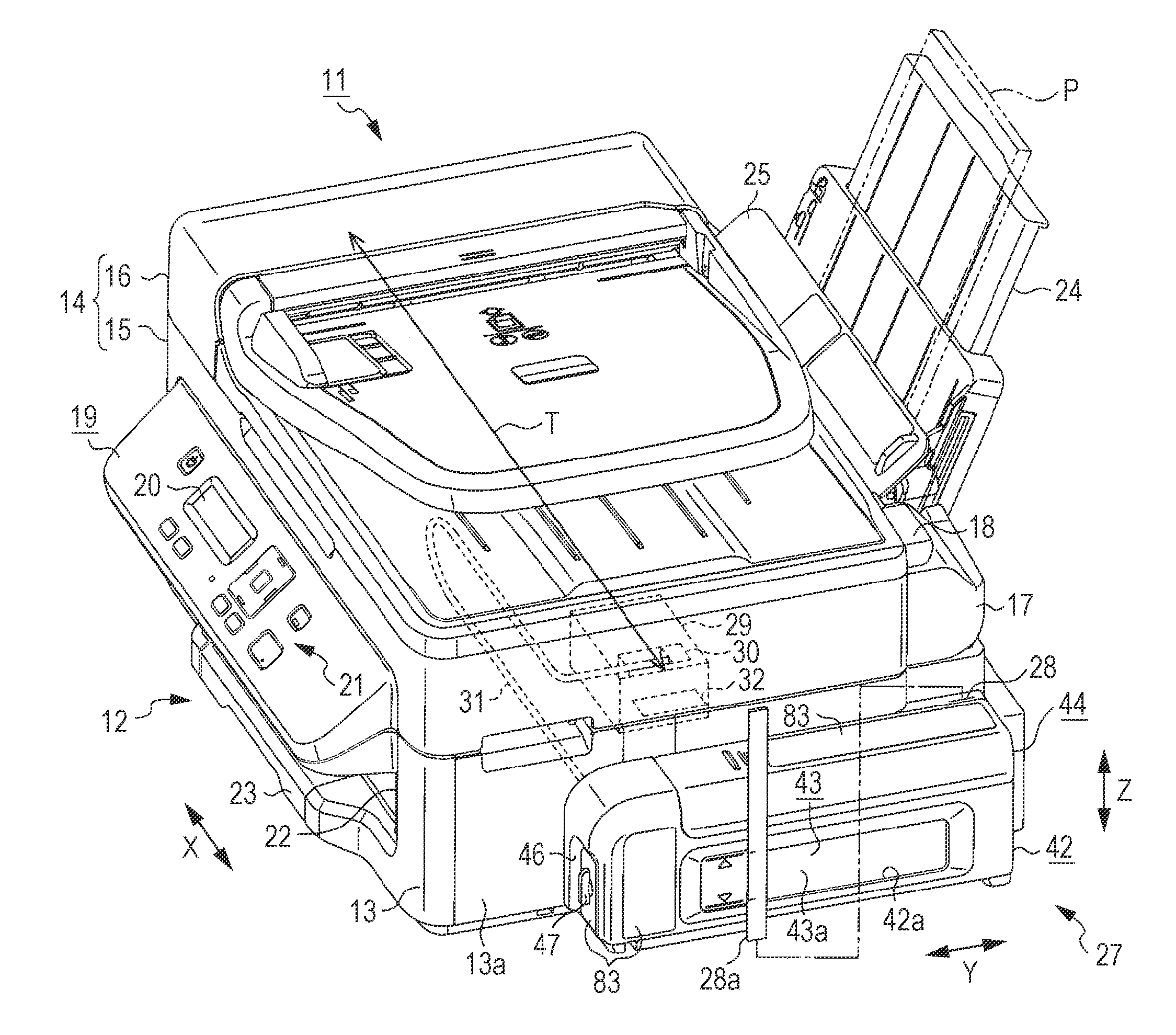
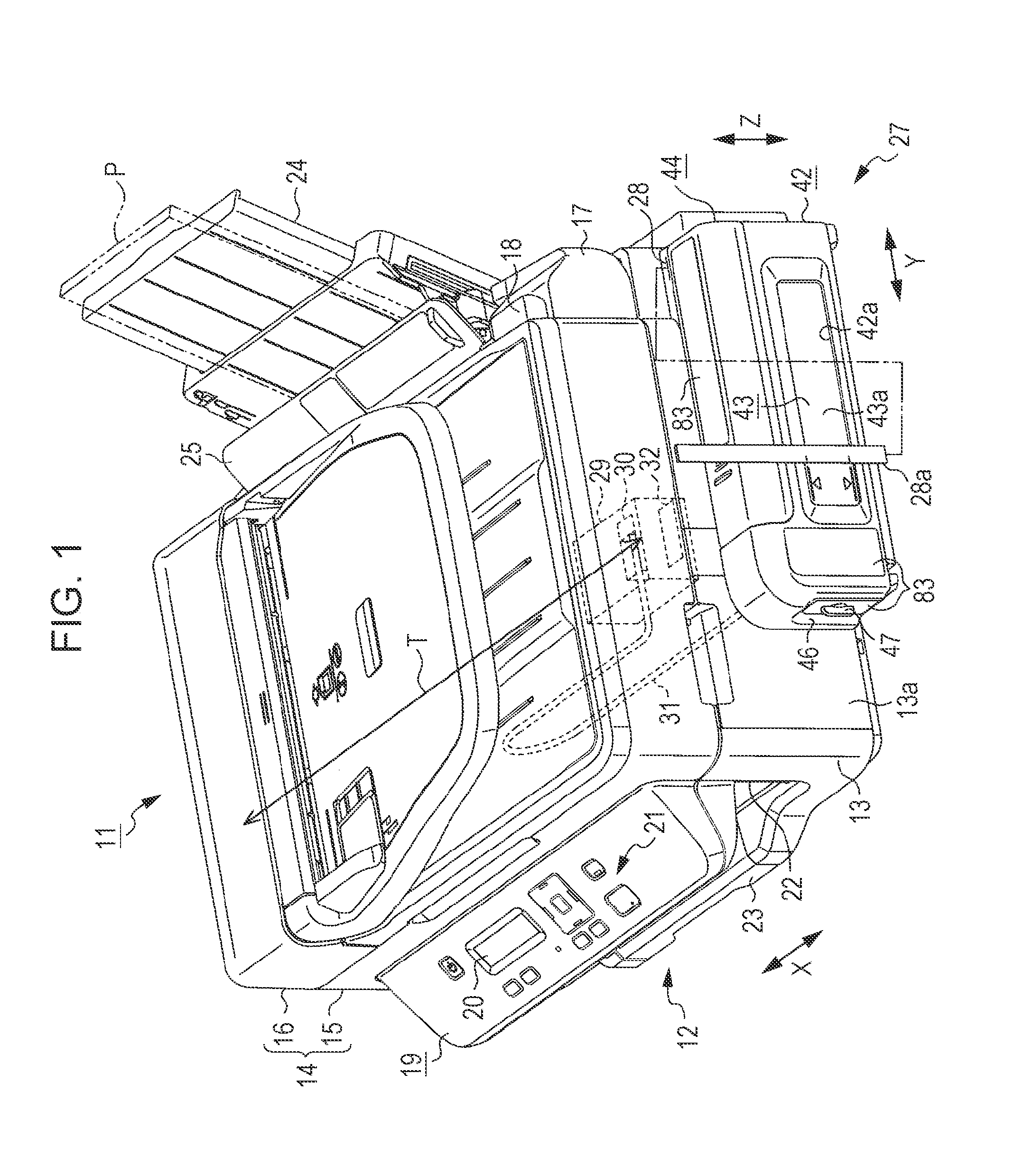
[0363]As illustrated in FIG. 1, a multi-function printer 11 includes a recording apparatus 12 and a scanner unit 14 mounted on an apparatus main body 13, which is an example of a housing of the recording apparatus 12.

[0364]The recording apparatus 12 can perform recording on a sheet P which is an example of a recording medium, while the scanner unit 14 can read out an image recorded on a manuscript. In the description, the direction opposite to the direction of gravity is referred to as an upward direction, and the direction of gravity is referred to as a downward direction. In addition, the direction in the upward direction and downward direction are illustrated by an vertical direction Z, which is an example of the vertical direction.

[0365]The scanner unit 14 includes a scanner main body 15, a portion of whi...

example 1

[0508]An example of the ink tank 43 will be described.

[0509]As illustrated in FIGS. 23 and 24, the ink tank 43 is configured to include a bottomed box-shaped container case 48 and a film 49. The container case 48 has a container opening portion 48a, which is an example of an opening portion, disposed on one surface side. The film 49 is an example of a thin film member. Five surfaces of the container case 48 are integrally molded, and the film 49 is adhered to the container opening portion 48a of the container case 48. In this manner, the ink chamber 50, which is an example of a liquid containing chamber containing the ink, and an air chamber 200 allowing the ink chamber 50 to communicate with the air are formed.

[0510]The ink chamber 50 and the air chamber 200 are partitioned into an area of the air chamber 200 and an area of the ink chamber 50 by a partition wall 48b, which is formed to extend in a direction (front / rear direction Y) following the bottom surface of the container case...

second embodiment

[0685]Next, a second embodiment of the invention will be described with reference to the accompanying drawings. The second embodiment is different from the first embodiment in that the scanner unit 14 is not provided. Then, since the other elements are substantially the same as those of the first embodiment, the repeated description will be omitted by giving the same reference numerals to the same configuring elements.

[0686]As illustrated in FIG. 53, a recording apparatus 85, which is an example of a liquid consuming apparatus, includes an operation button 86 in the front surface side. At a position which is below the operation button 86 in the recording apparatus 85, a discharge port 88 is open in order to discharge a sheet P from the inside of an apparatus main body 87, which is an example of a housing. In addition, a removable sheet discharge tray 89 is accommodated below the discharge port 88 in the recording apparatus 85. Furthermore, a pivot type medium support body 90 on whic...


PUM


Abstract

A liquid container includes an ink chamber containing an ink to be supplied via a tube to a liquid ejecting head consuming the ink; an outlet port from which the ink contained in the ink chamber flows to the tube side; an injection port through which the ink can be injected into the ink chamber; and an air intake port taking air into the ink chamber from a further vertically upper position than a liquid level of the ink when the ink is contained in the ink chamber. If the ink equal to 5% of containing capacity containable in the ink chamber flows from the outlet port, the liquid container has an area where a fluctuation range of the liquid level of the ink inside the ink chamber becomes 5% or less of the cubic root of the containing capacity.

Description

BACKGROUND[0001]1. Technical Field[0002]The present invention relates to a liquid container, a liquid consuming apparatus, a liquid supply system and a liquid container unit.[0003]2. Related Art[0004]In the related art, an ink jet recording apparatus (liquid consuming apparatus) has been known which includes a main tank (liquid container) containing an ink (liquid) consumed by a recording head (liquid consuming unit, liquid ejecting head) (for example, refer to JP-A-2000-301732). The main tank includes an air communication hole (air intake port) which can take outside air into an ink chamber when the amount of the ink contained in the ink chamber decreases due to the consumption of the ink. The air communication hole is formed at a vertically upper position in the ink chamber in order to suppress the outside intake air from being dissolved into the ink.[0005]In addition, in the related art, an ink jet recording apparatus (liquid consuming apparatus) has been known which includes an ...

Claims


Application Information

Patent Timeline
Patent Type & Authority Applications(United States)
IPC IPC(8): B41J2/175
CPCB41J2/17556
Inventor KUDO, SHOMAKOASE, TAKASHIOKADA, TOSHIYAKOIKE, YASUNORITAKAMOTO, TETSUYASUZUKI, NOBUTAKATAMAI, SATOSHINAKAZAWA, TORUTSUKAHARA, KATSUTOMOKANAZAWA, MASAYUKIMIMURA, NAOFUMIIIZAWA, KEIGOKOBAYASHI, YUTAKA
Owner SEIKO EPSON CORP
Why Eureka
Try Eureka