Method of manufacturing the piezoelectric transducer

a manufacturing method and piezoelectric technology, applied in the field of piezoelectric transducers, can solve the problems of increasing the cost of a power source or a driving circuit board, and achieve the effect of high-quality printing

Inactive Publication Date: 2006-02-07
BROTHER KOGYO KK
View PDF5 Cites 20 Cited by
  • Summary
  • Abstract
  • Description
  • Claims
  • Application Information

AI Technical Summary

Benefits of technology

[0011]The present invention addresses the forgoing problems and provides a piezoelectric transducer for use in an ink ejector, in which areas to be deformed are deformed by a substantially uniform amount and an ink droplet is ejected at a substantially uniform velocity even when a constant drive voltage is applied to all the areas to be deformed, thereby accomplishing high-quality printing.

Problems solved by technology

The forgoing problems could be solved, for example, by changing the drive voltage for each area to be deformed, but this method would increase the costs of a power source or a driving circuit board.

Method used


Image

  • Method of manufacturing the piezoelectric transducer
  • Method of manufacturing the piezoelectric transducer
  • Method of manufacturing the piezoelectric transducer

Examples


first embodiment

[0032]A piezoelectric transducer, an ink ejector, and an ink-jet printer will be described with reference to FIGS. 1 through 3.

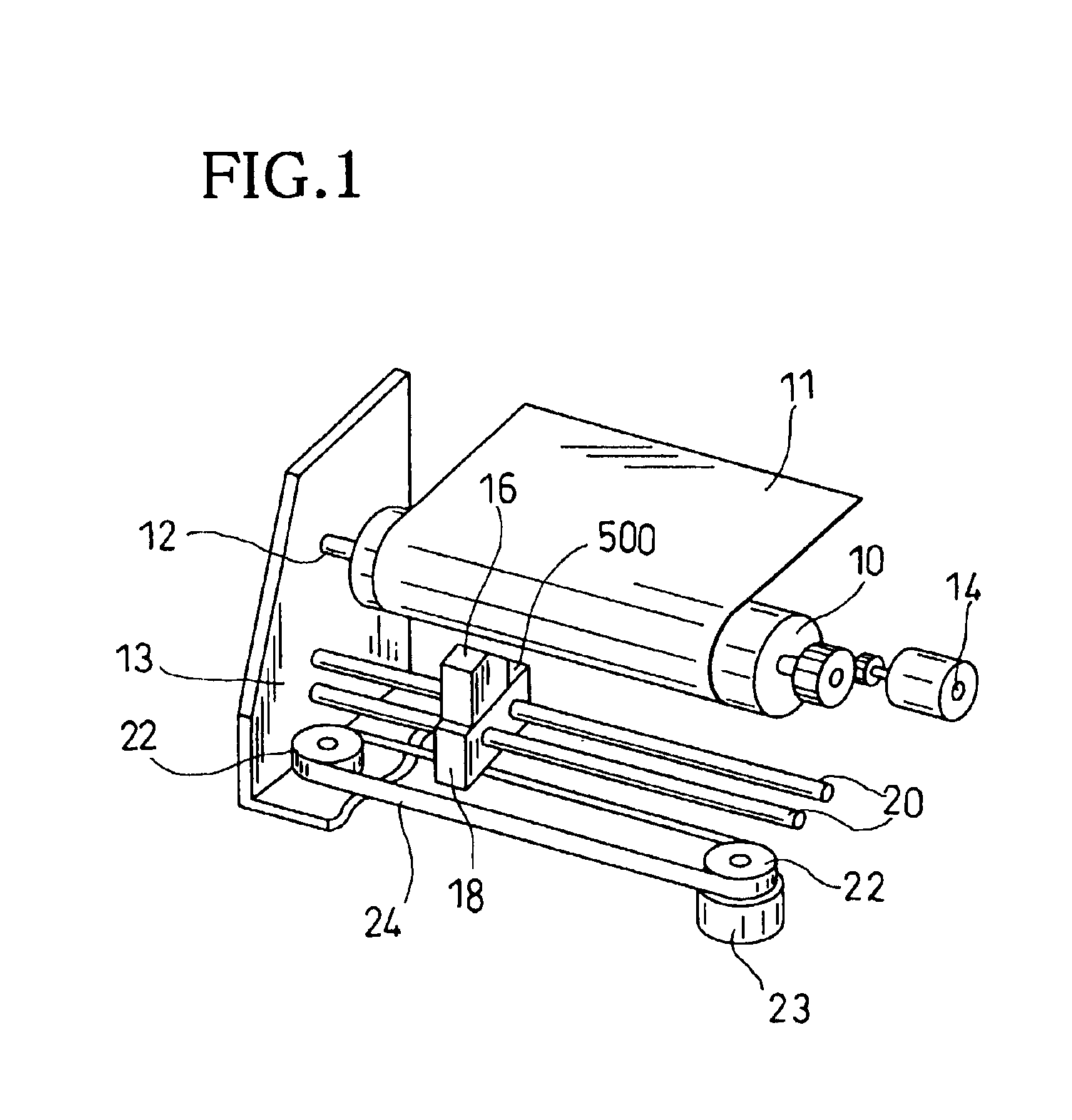
[0033]FIG. 1 is a perspective view showing substantial elements of an ink-jet printer incorporating an ink ejector 500 of the first embodiment. A platen 10 is rotatably attached to a frame 13 via a shaft 12 and is driven by a motor 14. An ink ejector 500, which will be described later herein, is disposed to face the platen 10. The ink ejector 500 is mounted on a carriage 18 together with an ink source 16. The carriage 18 is slidably held by two guide rods 20 disposed parallel to the axis of the platen 10, and is connected to a timing belt 24 attached around a pair of pulleys 22. The motor 23 rotates one of the pulleys 22 to feed the timing belt, thereby moving the carriage along the platen 10.

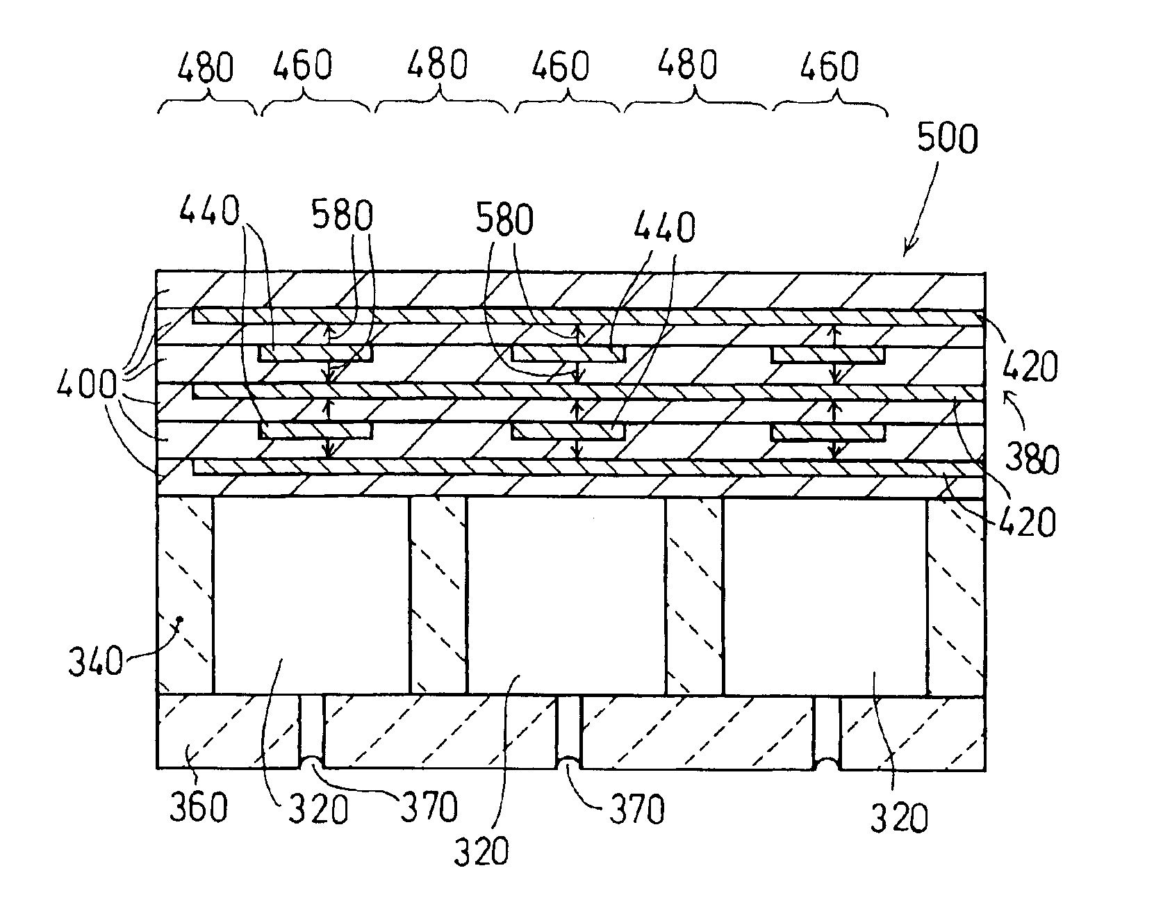
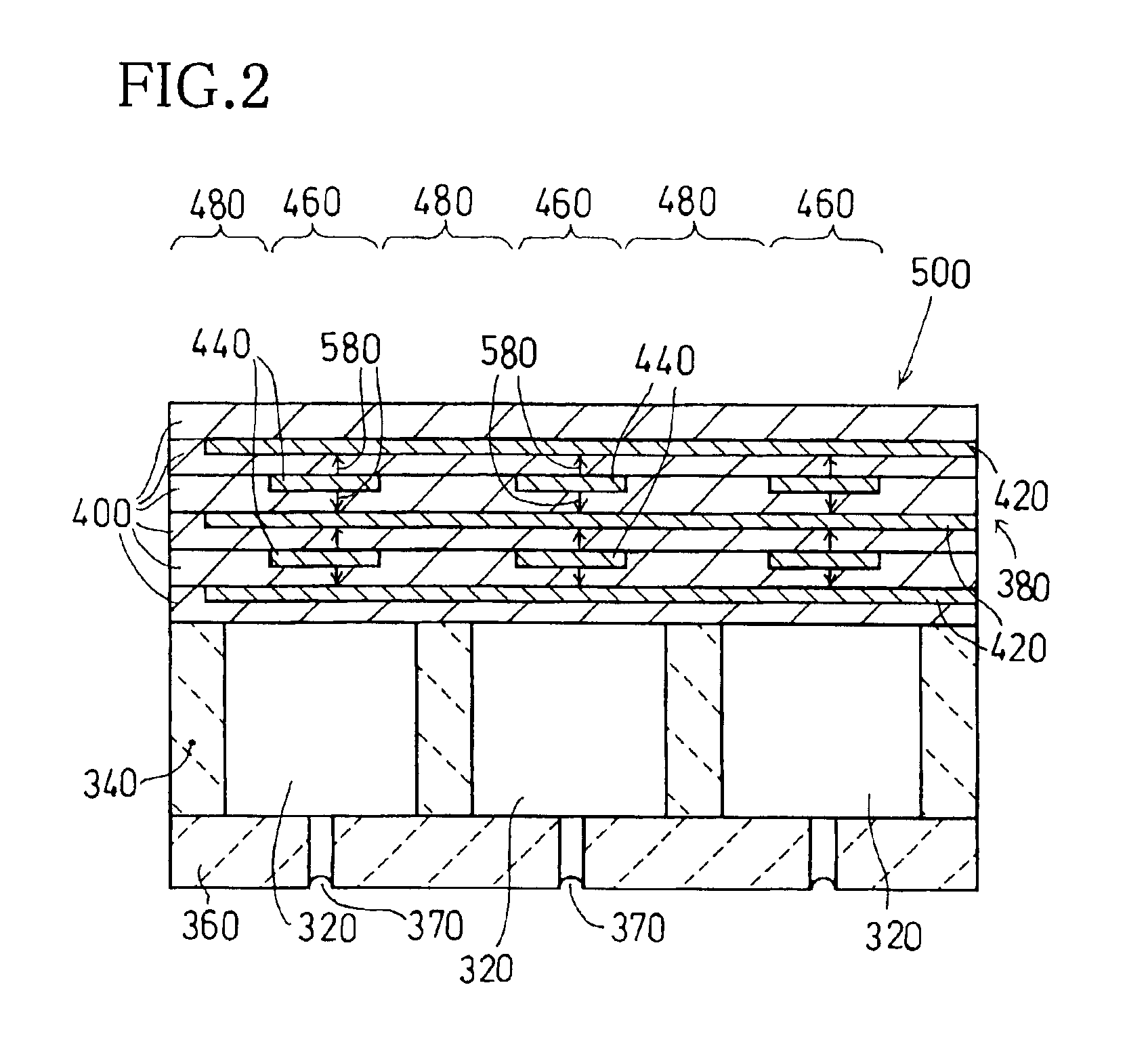
[0034]FIG. 2 is a sectional view of the ink ejector 500. The ink ejector 500 includes an ink channel member 340, which is a rectangular box open at the top and bottom ...

second embodiment

[0055]the invention will be described with reference to FIGS. 10A-10C. As shown in FIG. 10A, inner electrodes 130 as a first set of electrodes and inner electrodes 140 as a second set of electrodes are provided alternately in a plurality of piezoelectric ceramic layers 400, at predetermined intervals, in the direction of an array of ink channels. In this embodiment, the first and second set of electrodes are stacked at predetermined intervals in the thickness direction of the piezoelectric ceramic layers 400. A pair of sets of inner electrodes 140, 140 are placed on partition walls (ink channel member 340) on both sides of each ink channel 320. A set of inner electrodes 320 is placed at the center of each ink channel 320.

[0056]Areas defined in the piezoelectric ceramic layers 400 between a set of inner electrodes 130 and a pair of sets of inner electrodes 140, 140 are polarized as active areas 160, 160, as shown by arrows 150. When an ink droplet is to be ejected selectively from an...

third embodiment

[0060]the invention will be described with reference to FIGS. 11A, 11B, and 11C. A pair of sets of inner electrodes 140, 140 are placed on partition walls (ink channel member 340) on both sides of each ink channel 320. A set of inner electrodes 130 is placed at the center of each ink channel 320. In this case, sets of inner electrodes 130, 140 are used as polarizing electrodes. Each area defined between a set of inner electrodes 130 and a set of inner electrodes 140 is polarized as an active area 250, as shown by arrow 290, in an opposing direction of the sets of inner electrodes 130, 140.

[0061]Outer drive electrodes 260, 270 are formed on the outer surfaces of the top and bottom of the piezoelectric transducer 280. In this case, an outer common electrode 270 is formed throughout the bottom surface to face the ink channels 320, and outer individual electrodes 260 are formed separately to cover the respective active areas 250 of the respective ink channels 320.

[0062]When an ink dropl...


PUM

PropertyMeasurementUnit
temperatureaaaaaaaaaa
electric fieldaaaaaaaaaa
widthaaaaaaaaaa

Abstract

Inner individual electrodes are formed at intervals on a piezoelectric ceramic layer so as to correspond in a one-to-one relationship with ink channels, and an inner common electrode are formed on another piezoelectric ceramic layer. The required number of piezoelectric ceramic layers with inner individual electrodes and with an inner common electrode are laminated alternately. An outer common electrode is connected to the inner common electrodes, and outer individual electrodes are connected to the respective inner individual electrodes. The capacitance between the outer common electrode and each of the outer individual electrodes is measured. A polarization electric field adjusted based on the measured value is applied between the common electrode and each of the outer individual electrodes to perform polarization. As a result, each area defined over an ink channel by the stacked inner individual and common electrodes is polarized so as to be deformed by a uniform amount when a constant drive voltage is used.

Description

BACKGROUND OF THE INVENTION[0001]1. Field of Invention[0002]The invention relates to a piezoelectric transducer for use in an ink ejector and relates to a method of manufacturing the piezoelectric transducer.[0003]2. Description of Related Art[0004]A piezoelectric ink ejecting mechanism has been conventionally proposed for a printhead. In a drop-on-demand ink ejecting mechanism, a piezoelectric transducer deforms to change the volume of an ink channel containing ink. Ink in the ink channel is ejected from a nozzle when the volume is reduced, while ink is drawn into the ink channel when the volume is increased.[0005]A single piezoelectric transducer having a plurality of ink ejecting mechanisms and disposed across a plurality of ink channels has recently been proposed for a piezoelectric ink ejector. A portion of the piezoelectric transducer corresponding to a particular ink ejecting mechanism is locally deformed. Such a piezoelectric transducer is disclosed in U.S. Pat. No. 5,402,15...

Claims


Application Information

Patent Timeline
Patent Type & Authority Patents(United States)
IPC IPC(8): H04R17/00B41J2/14B41J2/16H01L41/22H01L41/257
CPCB41J2/14209B41J2002/14217B41J2002/14225Y10T29/42Y10T29/4902Y10T29/4908Y10T29/49172Y10T29/49194Y10T29/49002Y10T29/49005
Inventor TAKAHASHI, YOSHIKAZU
Owner BROTHER KOGYO KK
Why Eureka
Try Eureka