Magnetic head slider with flying height control

a slider and magnetic head technology, applied in the field of magnetic head sliders, can solve the problems of increasing the offset ratio of flying height caused by deformation, changing the state of generation of flying force on the air bearing surface, and increasing the control power is not desirable, so as to reduce the offset ratio of flying height

Inactive Publication Date: 2007-03-15
WESTERN DIGITAL TECH INC
View PDF16 Cites 15 Cited by
  • Summary
  • Abstract
  • Description
  • Claims
  • Application Information

AI Technical Summary

Benefits of technology

[0011] According to the present invention it is possible to decrease the offset ratio in flying height of a magnetic head slider having a flying height control mechanism.

Problems solved by technology

In the magnetic head slider having a flying height control mechanism in the vicinity of the magnetic transducer, which is described in Patent Document 1, however, when the flying height control mechanism is operated, the air bearing surface located near the magnetic transducer is projected and deformed out of plane, causing a change in the state of generation of a flying force on the air bearing surface.
Such an increase of the control power is not desirable for the magnetic disk drive for which the operation at a low power consumption is required more and more strongly.
Further, a smaller magnetic head slider used in a small-sized magnetic disk drive has a tendency that an area ratio of the projectingly deformed region on the air bearing surface increases and so increases the offset ratio in flying height caused by deformation.
However, the portion which generates the highest pressure on the air bearing surface lies on the rail surface including the magnetic transducer and there occurs a change in flying force caused by projecting deformation, not attaining a fundamental air bearing surface structure able to decrease greatly the offset ratio of flying height.

Method used


Image

  • Magnetic head slider with flying height control
  • Magnetic head slider with flying height control
  • Magnetic head slider with flying height control

Examples


Embodiment Construction

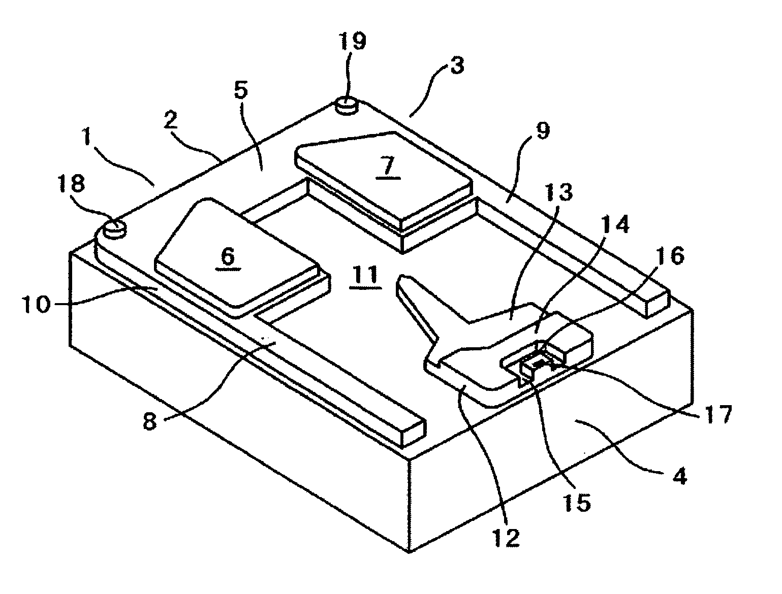
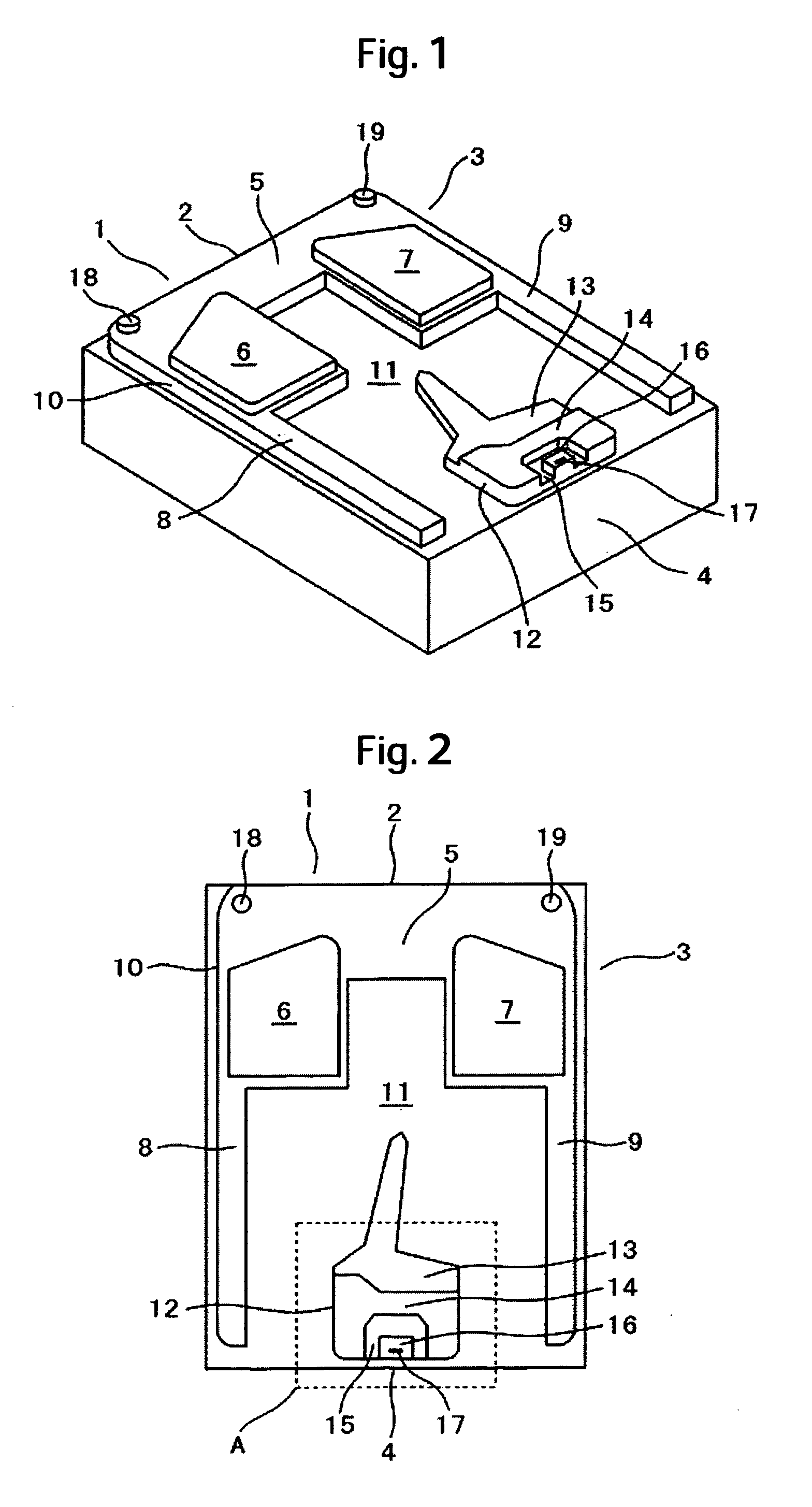
[0037]FIGS. 1 and 2 are a perspective view and a plan view, respectively, of a magnetic head slider according to a first embodiment of the present invention. The magnetic head slider (slider) 1 has a length of 1.25 mm, a width of 1.0 mm and a thickness of 0.3 mm. The slider 1 includes a leading edge 2, an air bearing surface 3, and a trailing edge 4. The air bearing surface 3 includes a front pad 10, the front pad 10 being made up of a leading-side step bearing surface (front step bearing surface) 5 contiguous to the leading edge 2, leading pads 18 and 19 formed on both sides of the leading edge 2 in the front step bearing surface 5, leading rail surfaces 6 and 7 contiguous to the front step bearing surface 5, and side step bearing surfaces 8 and 9 having the same depth as the depth of the front step bearing surface 5. The air bearing surface 3 also includes a negative pressure groove surface (deep groove surface) 11 surrounded by the front pad 10. The air bearing surface 3 further ...


PUM

PropertyMeasurementUnit
angle of inclinationaaaaaaaaaa
thicknessaaaaaaaaaa
widthaaaaaaaaaa

Abstract

Embodiments of the invention provide a slider structure able to lower a flying height compensation ratio caused by a projecting deformation of an air bearing surface of a slider by a flying height control mechanism and afford a change in flying height with a low control power. In one embodiment, a slider is provided with a leading edge, an air bearing surface, and a trailing edge. The air bearing surface includes a front pad, the front pad being made up of a front step bearing surface, leading rail surfaces, and side step bearing surfaces. The air bearing surface also includes a negative pressure groove surface surrounded by the front pad. The air bearing surface further includes a rear pad, the rear pad being made up of a rear step bearing surface formed at the same depth as the depth of the front step bearing surface and positioned on the trailing edge side, a trailing rail surface, an intermediate groove deeper than the trailing rail surface, and a trailing pad surface lying at the same height as the trailing rail surface. The front and both sides of the trailing pad surface are surrounded by the trailing rail surface.

Description

CROSS-REFERENCES TO RELATED APPLICATIONS [0001] This application claims priority from Japanese Patent Application No. JP2005-261831, filed Sep. 9, 2005, the entire disclosure of which is incorporated herein by reference. BACKGROUND OF THE INVENTION [0002] The present invention relates to a magnetic head slider and a magnetic disk drive carrying the magnetic head slider thereon. More particularly, the present invention is concerned with the shape of an air bearing surface of a magnetic head slider. [0003] A magnetic head slider, which is adapted to fly over a rotating disk recording medium while maintaining a slight spacing (flying height) with respect to the disk, is used in a magnetic disk drive. Usually, the magnetic head slider is provided at a trailing edge of a slider with a magnetic transducer for write and read of information to and from a disk recording medium. In order to enhance the memory capacity, it is required for a magnetic disk drive to further increase the bit (reco...

Claims


Application Information

Patent Timeline
Patent Type & Authority Applications(United States)
IPC IPC(8): G11B5/60G11B21/22
CPCG11B5/6064G11B5/6005
Inventor HASHIMOTO, KIYOSHIKOHIRA, HIDEKAZUYAMAZAKI, TAKANORIMIYAKE, KOJI
Owner WESTERN DIGITAL TECH INC
Why Eureka
Try Eureka